Rear Axle Load and Jib Angle: The Two Numbers That Decide a Safe Bin Lift
On soft ground, the outcome of a bin lift is settled before the hydraulics engage, by two figures: the rear axle load and the jib angle. Together they decide whether the chassis stays supported or starts to sink, tip, or slide once the cable tensions and the weight moves rearward. The engineering here is load distribution and ground-bearing pressure. An experienced driver can get away with rough judgement on firm pavement; on saturated soil, gravel, or backfill it will not hold. The rear axle carries the transferred weight, and the jib angle sets the reach and the moment arm that drives the transfer – geometry that begins with the subframe and lift cylinder at the centre of the mechanism. This article works through the loads and the geometry so both numbers can be calculated before the truck leaves the yard.
How Rear Axle Load Develops Before the Lift
Every kilogram of a loaded container follows a defined path from the container rails into the ground beneath the rear tires. That path runs through four structural elements: the chassis, the subframe, the rear hinge, and the tilt cylinder. Where the load lands, and when, tells you which axle is doing the work.

The Load Path, Step by Step
- The chassis carries the subframe on its rails and distributes the vertical reaction between the front and rear suspension.
- The subframe takes the bin’s weight directly. Rail spacing, mounting height, and hinge position set the moment arm that decides how much of that weight reaches the rear axle.
- The rear hinge anchors the tilt pivot at the tail of the frame. As the subframe rotates, the hinge becomes the main transfer point, turning angular motion into a concentrated vertical and horizontal reaction above the rear axle.
- The tilt cylinder supplies the lifting force. Its angle to the subframe changes through the stroke, so the rearward component peaks early and falls away as the bin rises.
Why Break-Out Peaks, Not Steady Lift
A container that has sat for days has settled into the ground, and its rails have bonded to the contact surfaces. Breaking that bond is the highest-load event in the cycle: the cylinder has to overcome static friction and the full bin mass while the effective moment arm is at its shortest and the load is still fully forward of the rear axle.
Once the bin “breaks free” and rotates, sliding friction replaces static friction, and the centre of gravity moves rearward and upward, putting more of the reaction onto the rear suspension. The result is a brief spike. A representative 25-tonne payload can push the rear axle load from roughly 52% of GVW at rest to about 71% during break-out, then settle back toward 57-60% as the bin approaches full tilt.
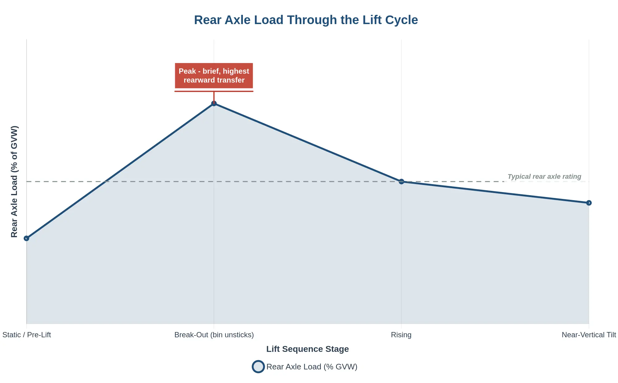
| Lift stage | Approximate rear axle load (% GVW) |
|---|---|
| Static / pre-lift | 52 |
| Break-out (bin unsticks) | 71 |
| Rising | 60 |
| Near-vertical tilt | 57 |
Why the Rear Axle Governs on Soft Ground
The steer axle is rarely the problem. Its share of the load falls as the bin tips rearward, so it unweights exactly when you would want it planted. The rear axle is the opposite: it collects the transferred mass just as the ground beneath it is weakest. On soft or saturated soil, bearing capacity fails first at the rear tire contact patch, where pressure is highest and the ground has already been disturbed by the trailer set-down and by earlier passes over the same spot.
Soft-ground planning is therefore rear-axle planning. Rutting, sinkage, and eventual tipping all begin at the rear wheels, not because they are overloaded at rest, but because the break-out spike arrives on ground that cannot mobilise the reaction quickly enough.
Why Upfit Choices Matter
The subframe defines hinge position, cylinder mounting angle, and the moment arms, so upfit decisions reshape the load path. Moving a hinge, changing rail height, or choosing a different cylinder stroke can shift axle load by several percentage points in either direction. Before buying or re-speccing a chassis, review the subframe and lift-cylinder checks that separate a soft-ground-friendly upfit from a marginal one.
For operators, the practical rule is to plan the lift around the break-out peak rather than the steady-state figure, and to treat the rear axle as the limiting constraint whenever the ground is anything but firm.
Ground Condition Reference: Bearing Pressure vs. Rear Axle Load
Before committing a jib angle or boom extension, the usual limiting factor is how much load the ground can take beneath the outriggers and rear axle. Load passes from the hook lift through the subframe and lift cylinder assembly into the chassis, and from there into whatever the tyres and pads rest on. The table pairs common ground conditions with indicative bearing pressures, a realistic rear axle load for a loaded hooklift truck (typically 10 to 14 tonnes on the rear bogie, depending on bin payload and jib angle), and the matching mitigation.
| Ground Condition | Typical Allowable Bearing Pressure (kPa) | Approx. Rear Axle Load Under Load (kg) | Recommended Bearing Mat / Action |
|---|---|---|---|
| Firm compacted gravel (well-graded, rolled) | 200 – 300 | 11,000 – 13,000 | Standard outrigger pads (300 – 400 mm); no matting required for short-duration lifts |
| Wet clay (soft to firm, undrained) | 50 – 100 | 11,000 – 13,000 | Timber cribbing plus 1.2 m load-spreading mats; re-check pad settlement before lifting |
| Loose sand / gravel (uncompacted fill) | 100 – 150 | 11,000 – 13,000 | Heavy-duty load-spreading mats or steel spreader plates to increase contact area |
| Soft waterlogged soil | 25 – 50 | 12,000 – 14,000 | Engineered matting or steel plates; reduce jib angle, or re-site the truck to firm ground |
| Peat / organic fill | 10 – 25 | 12,000 – 14,000 | Abort the lift or reposition to firm ground – matting cannot reliably spread this load |
| Reinforced concrete hardstanding (intact) | 300 – 500 | 11,000 – 13,000 | Outrigger pads only; verify slab thickness and stay clear of un-reinforced edges |
All figures are indicative only and must be confirmed against a site-specific geotechnical assessment before any lifting operation.
Ground-Bearing Pressure: Why Soft Ground Fails Under the Rear Axle
Ground-bearing pressure is the load carried per unit area of soil beneath the tires. Divide the rear axle load by the total tire contact patch area:
Ground-bearing pressure (psi) = Rear axle load (lb) ÷ Total contact area (in²)
The table shows how the same truck behaves differently when the tire footprint changes. The axle load stays fixed; only the contact area moves.
| Rear axle load (lb) | Tires | Contact patch per tire (in²) | Total contact area (in²) | Ground-bearing pressure (psi) |
|---|---|---|---|---|
| 18,000 | 4 | 60 | 240 | 75 |
| 18,000 | 4 | 90 | 360 | 50 |
| 22,000 | 4 | 60 | 240 | 92 |
| 22,000 | 4 | 90 | 360 | 61 |
When Pressure Exceeds Allowable Bearing Capacity
Every soil has an allowable bearing capacity: the pressure it can sustain before it shears. Soft saturated clay may hold only 7-14 psi (1,000-2,000 psf). At 75 psi the rear axle is already past that limit, so the soil fails and the tire sinks.
As the tire sinks it pushes soil forward and sideways, producing ruts. Because the rear axle carries the lift point, sinkage there lowers and tilts the rear of the chassis. That tilt moves weight onto the side that is already sinking, deepening the rut and creating lateral instability: the truck leans, the outriggers or stabilisers lose contact, and the moment of the lifted load can pull the frame further downhill.
The consequence is not just a stuck truck. A tilted chassis changes the lift arc, so the bin or container lands off-centre or misses the rail. Tilt geometry also varies by body type: a hooklift vs cable hoist geometry places the pivot and load path differently, so where the load lands on soft ground shifts with the design.
Spreading the Load Without Changing the Load
Mats, cribbing, and larger plates lower ground-bearing pressure without reducing the axle load. A 2×8 ft mat under the rear axle expands the effective contact area from roughly 240 in² to over 2,300 in², cutting 75 psi to under 8 psi. The load is unchanged; only the area carrying it has grown. Always confirm the mat area against the soil’s allowable capacity before committing to the lift.
Rear Axle Load vs Jib / Tilt Angle During Break-Out
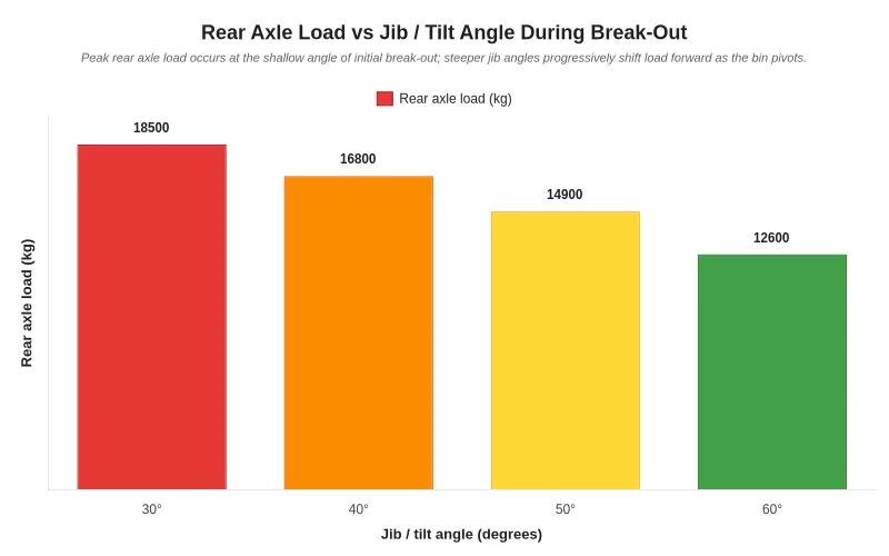
The rear axle carries its heaviest load at the shallow angles, where the bin first breaks out of its seated position. At 30 degrees it sees roughly 18,500 kg, and that figure falls steadily as the jib tilts further, down to 12,600 kg at 60 degrees. The reason is geometric. During the initial break-out the hook pulls almost straight down and back, keeping most of the bin’s mass over the rear bogie. As the jib angle steepens and the bin pivots forward, the load’s centre of gravity moves ahead of the rear axle and toward the front of the chassis.
On soft or unstable ground, this is the number that sets the safety margin. The critical moment is not the fully raised bin but the instant the load breaks out of its cradle. That is when the cargo presses hardest on the ground beneath the rear tires, driving the highest ground-bearing pressure and the greatest risk of rutting, sinkage, or differential settling. If the surface can hold 18,500 kg at 30 degrees, it will only get easier as you tilt further.
Two rules follow from the data:
- Plan the approach around the shallow angle. Expect peak rear axle load at the start of the lift; the load does not get heavier once the bin is airborne.
- Match ground preparation to the peak, not the average. Reinforce, spread, or reposition the truck for the worst-case figure at initial break-out, when the surface is most likely to fail.
Because the load moves forward through the lift, chassis geometry and subframe condition matter a great deal on a hooklift. When inspecting a used unit, these subframe and lift-cylinder checks show whether the truck can take the concentrated rear-axle forces that break-out demands.
Jib Angle and Safe Lifting Geometry
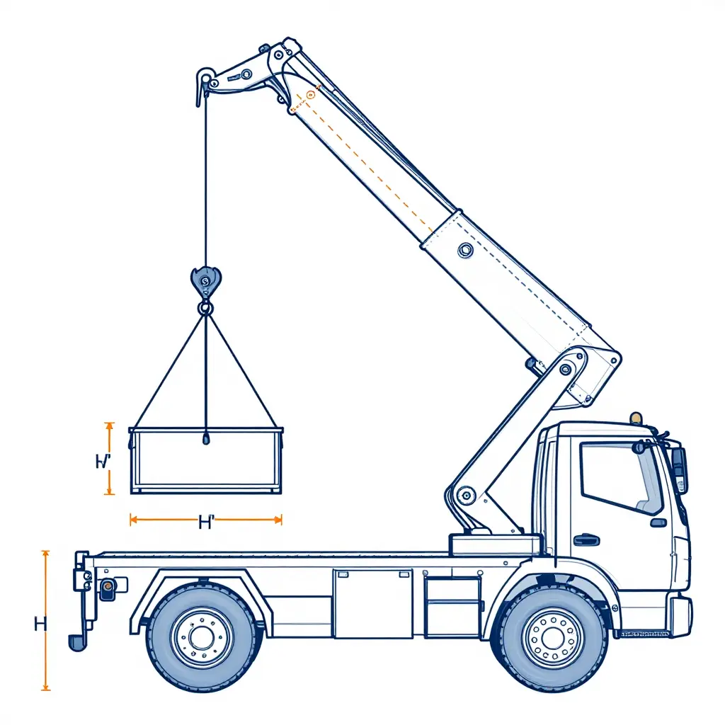
The jib angle at first hook engagement sets the geometry for the whole lift. That angle fixes the horizontal offset between the hook and the rear hinge, and the offset is the moment arm that turns the load into a rotational force about the rear axle and rear hinge. Because the bin is still fully grounded, with its full mass available as resistance, the peak moment arm rather than the peak hydraulic pressure governs the worst-case load on the rear axle and hinge pins.
Too Shallow: The Horizontal Component Grows
A shallow jib angle tilts the pull toward horizontal: the horizontal component of hook force rises while the vertical lift component falls. Breaking the bin’s rails off the ground means overcoming friction and the rail-to-deck shear, so the required break-out force climbs sharply. That force acts at a longer effective lever from the hinge, and the rear axle absorbs the reaction. On soft ground the risk compounds, because a higher break-out force means more downward load on bearing pressure that is already marginal.
Too Steep: Interference and Wandering Centre of Gravity
A steep jib angle reduces horizontal reach, but it brings the bin’s lower rail and body close to the jib and rear frame, creating interference and a hard-stop that can stall the lift or damage the bin. It also moves the effective line of action rearward and shifts the combined centre of gravity forward over the front axle, which is hard to predict mid-lift. On an already nose-heavy rig, that shift can unload the rear tyres just when traction is needed most.
Setting and Verifying the Angle Before the Lift
Use the manufacturer’s specified jib and tilt angles as the baseline, then verify against the actual bin on the actual chassis.
| Check | Purpose |
|---|---|
| Confirm jib/tilt angle indicator or mechanical stop | Establishes the reference geometry |
| Match bin rail length to the jib travel | Prevents short-rail interference and long-rail overreach |
| Confirm hook engagement depth before tension | Avoids point-loading the hook |
| Verify rear-axle and hinge rating against the peak moment arm | Confirms structural margin |
| Assess ground bearing at the rear axle footprint | Confirms the reaction can be supported |
Bin-to-chassis matching is a geometry constraint in its own right: a bin that is too short or too long for the subframe forces a non-optimal jib angle, and technique cannot compensate for mismatched geometry. Get that relationship right first by reviewing matching bin size to chassis length, then commit to the lift only after the jib angle, hook engagement, and ground bearing are confirmed.
Torque on the rear hinge is load times moment arm. Control the arm at engagement and the rest of the lift follows predictably.
The diagram below isolates the two variables that govern a hook lift pick on soft ground: where the load sits on the chassis, and how the jib angle shapes the moment arm before the hydraulics take full tension. Read it as a free-body sketch; the point is to show the forces before the wheels start to sink.
Reading the diagram
- Front axle (A) and rear axle (R) are marked as vertical reference lines. Before the lift, the rear axle is the pivot for almost everything that follows.
- The bin and hook engagement point (C) sits behind the rear axle. The further the hook is from the chassis, the longer the lever arm acting on the rear axle.
- The jib/tilt angle (theta) is the angle between the jib arm and the chassis datum. A shallow angle raises the horizontal draw needed to break the bin free and the load the rear axle carries; too steep an angle risks interference with the bin.
- The rearward weight transfer arrow shows load moving toward the rear axle as tension builds.
- The downward reaction arrow at the rear axle is the ground-bearing demand the tires and subsoil must carry at that moment.
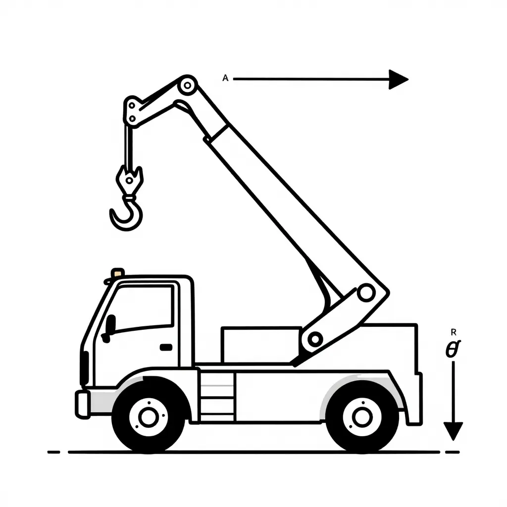
Why it matters on soft ground: the reaction grows before the bin moves. If ground-bearing pressure under the rear axle exceeds the soil’s capacity, the axle sinks, the effective tilt angle changes, and the geometry you calculated no longer holds. For more on how subframe and lift-cylinder condition affects these forces in practice, see our breakdown of the subframe and lift cylinder checks.
Quick geometry checklist
| Marker | What it represents | Watch for |
|---|---|---|
| A | Front axle | Front lift / light steering if transfer is extreme |
| R | Rear axle | Primary sink risk on soft ground |
| C | Hook engagement point | Distance from R sets the lever arm |
| theta | Jib / tilt angle | Too shallow = high draw force and rear-axle load; too steep = interference risk |
Use this sketch alongside your axle-load figures and ground-bearing assessment; it is the fastest way to sanity-check whether a pick is safe before you commit the hydraulics.
Field Procedure for Lifting on Soft or Unstable Ground
Soft ground turns a routine lift into a load-distribution problem. Work through this sequence in order; each step gates the next. Do not skip ahead because the ground “looks” firm.
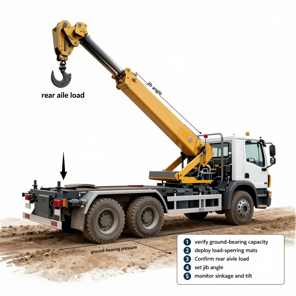
Step 1: Verify Ground-Bearing Capacity
Test the surface before the truck commits. Probe the ground with a penetrometer or bar, or set the loaded tires on a spot and watch for rutting. Find out what lies under the crust: soft clay, fill, saturated silt, and thawing subgrade all carry far less than compacted gravel. Establish an allowable bearing pressure in kPa (or psi) for that surface before moving any equipment.
Step 2: Deploy Load-Spreading Mats
Place mats, timber cribbing, or steel plates under every wheel that will carry the lift, not just the rear. Size them so the combined footprint brings ground-bearing pressure below the soil’s allowable limit. Overlap the mats and keep them level; a mat that rocks under load concentrates stress at its edge and is worse than no mat at all.
Step 3: Confirm Rear Axle Load Against Allowable Pressure
Run the numbers. Add the empty chassis weight, the bin or container weight, and the transferred load, then work out where the centre of gravity sits when the hook is under tension. The resulting rear axle load divided by the mat contact area must stay below the soil’s allowable pressure, with a safety margin. If it does not, spread the load further or reposition the truck on firmer ground. Operators who swap bins of differing sizes should study how bin size matches chassis length so these weights are never a guess.
Step 4: Set the Jib Angle
The jib angle controls both the lift vector and the moment applied to the rear axle. Set the boom to the manufacturer’s specified angle for the bin. A shallow jib keeps the pull closer to horizontal, which raises the break-out force and the load the rear axle carries, making it the worse end of the range on soft ground. A steeper jib lowers the rear-axle load but risks rail-to-jib interference and shifts the centre of gravity forward. Stay within the specified range, and confirm the tilt cylinder is fully seated before applying load.
Step 5: Monitor Axle Sinkage and Tilt During Break-Out
Break-out is the highest-risk moment. Watch the rear tires and the frame line as the hook tension comes on; a spotter standing outside the fall zone can call changes faster than a mirror. Watch for these stop signals:
| Warning Sign | What It Indicates | Required Action |
|---|---|---|
| Visible tire sinkage or fresh rutting under the rear wheels | Ground-bearing pressure exceeded | Stop, lower load, add mats |
| Frame tilt or a rising front axle | Rear axle overload, tipping moment rising | Stop, reduce jib angle, reposition |
| Bin shifting or sliding on the deck | Loss of traction, unstable lift geometry | Stop, reset the hook and line |
| Audible soil shear or drainage from the surface | Subsurface failure beginning | Abort the lift entirely |
| Cab listing, creaking, or unexpected movement | Progressive ground collapse | Abort and evacuate the fall zone |
Abort Criteria
Stop the lift immediately if the rear tires sink more than a few centimetres, the chassis tilts beyond level, the front axle begins to lift off the ground, the bin slides instead of lifting, or the operator hears or feels the ground shearing. Do not try to “push through” a sinkage event: a hook lift truck on soft ground can tip in seconds once the rear axle load shifts past the mat footprint. Lower the load, re-level the surface, add matting, and re-run the pressure calculation before restarting. An aborted lift costs less than a rolled chassis.
Pre-Lift Checklist: Rear Axle Load and Jib Angle on Soft Ground
Run through every line below before you raise the hook. Each item is a go/no-go gate: if a check fails, stop the lift, re-plan, or reposition the truck.
- Confirm the calculated rear axle load against the chassis-rated maximum before any lift begins, including the full bin and payload weight.
- Check the allowable ground-bearing pressure against the actual soil condition at every tire and outrigger footprint.
- Deploy bearing mats sized to the tire contact area to spread the load and prevent rutting or punch-through.
- Set the jib/tilt angle to the specified value for the load geometry, and record that setting before raising the hook.
- Inspect the rear hinge and lift cylinder for cracks, wear, or hydraulic leaks, following a structured subframe and lift cylinder inspection routine.
- Check the truck for level and cross-slope with a calibrated inclinometer, and keep slope within the manufacturer’s limit.
- Verify outrigger or cribbing placement so every pad has full, uniform contact with stable ground.
- Set a stop-work sinkage threshold and brief every crew member on the trigger point and the abort signal.
- Position the truck so the lift path avoids soft spots, voids, and un-compacted fill.
- Mark and clear the exclusion zone around the lifting arc before the hook takes load.
Controlling the Two Variables That Decide the Lift
Every calculation and check in this guide comes back to two variables you control before the hook moves: rear axle load and jib angle. Rear axle load is how much weight – the chassis, the bin, and the payload – bears down through the rear tyres. Jib angle is the geometry that converts the lift cylinder’s force into leverage and decides where that force lands. The ground you park on sets neither; both come from how you position, stage, and prepare the truck before lifting begins.
Ground-bearing pressure links the machine to the surface beneath it. It is not a third variable to chase: it is the outcome of the first two, spread across the contact patch, and its peak arrives at break-out, the instant the bin releases from the ground and the full load transfers onto the truck. Mats, pads, and cribbing manage the resulting pressure without changing the axle load. The pressure can be corrected; the physics cannot.
Standardise these checks. Treat rear-axle verification, jib-angle confirmation, and break-out staging as routine pre-lift practice rather than special-case caution reserved for soft ground. The reliability that CRRC-backed build quality brings to hooklift, tanker, garbage, and trailer products is real engineering – the same discipline captured in proper subframe and lift-cylinder checks – and it performs at its best when the operator’s method matches the machine’s capability.
A lift that is measured before it begins stays within its engineering limits. Controlling axle load, jib angle, and ground-bearing pressure is not paperwork; it is the difference between a routine pick-up and a preventable incident. Know your numbers, respect the break-out moment, and the surface you lift from will hold.