Fork Truck Lifting Hook: The Attachment That Sets the Real Load Limit
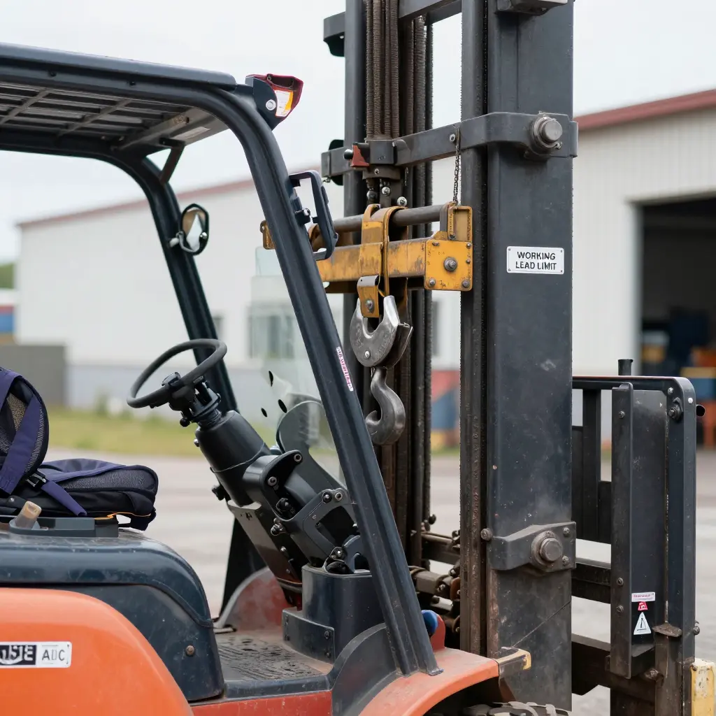
A fork truck lifting hook mounts to the carriage or fork tines of a powered industrial truck and turns the machine into a mobile rigging point. It gives the operator one engineered pick point above the load, which is how a forklift lifts things that will not sit on forks: engines, structural steel, precast panels, crated machinery.
The number stamped on that attachment is a rated capacity, and it is not the working load limit (WLL) you can actually pick in a real lift. Rated capacity assumes an ideal static load pulling straight down, in line with the pick point. Few lifts are that clean.
Two variables decide whether the lift stays inside a safe working envelope:
- Capacity derating – the reduction applied to rated capacity when the load is not lifted vertically, when the attachment sits off-center, or when worn or damaged hardware is in service.
- Sling angle limits – the rigging geometry. Widen the angle between sling legs and the tension in each leg multiplies, which lowers the effective WLL of the assembly.
A safe lift comes from reading both together. The nameplate alone will not tell you.
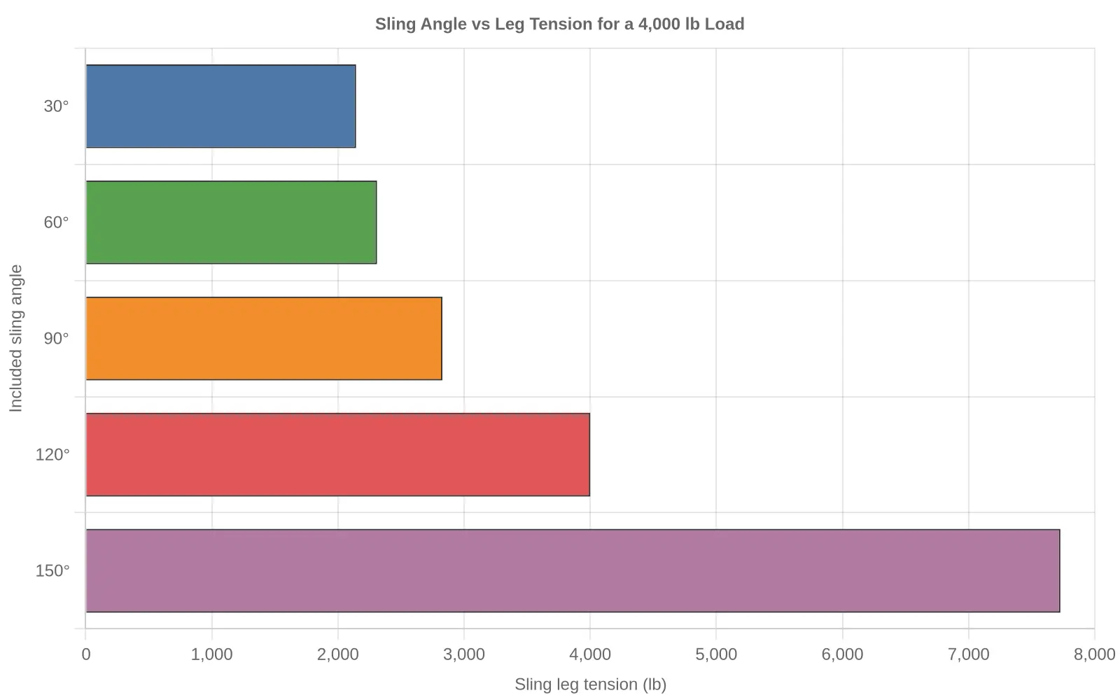
In the chart above, a 4,000 lb load on slings set at a 150-degree included angle puts roughly 7,727 lb of tension into each leg, nearly double the load’s own weight. The sections below work through the derating factors and the sling angle limits that follow from that. If you also manage lifting equipment across its full service life, it is worth reviewing subframe and lift cylinder inspection criteria alongside this.
The Engineering Basis of Capacity Derating
A hook on a forklift rarely sees a perfectly vertical, static pull. Capacity derating is the reduction of a hook’s allowable working load to cover the geometry, dynamics, and wear that no single tag number can describe. Skip it and you are working past the hook’s design intent without knowing it.
Rated Capacity vs. Derated Working Load
Every hook leaves the factory with a rated capacity: the most it holds under ideal, in-line tension. Subtract the margins for off-axis pulls, shock loads, and cyclic fatigue and you get the derated working load. The rated figure is a ceiling, not a target.
The load chart turns those limits into usable numbers for a given sling angle. Step outside the chart and the hook can yield.
Proof Load, Safety Factors, and the Fatigue Limit
Hooks are proof load tested, usually to about twice rated capacity, to confirm they carry the load without permanent set. On top of that sit design safety factors, often 4:1 to 5:1 against yield. Keep the load below the fatigue limit and the hook stays elastic. Repeated overload bends it into plastic deformation, and it does not come back.
Derating Triggers
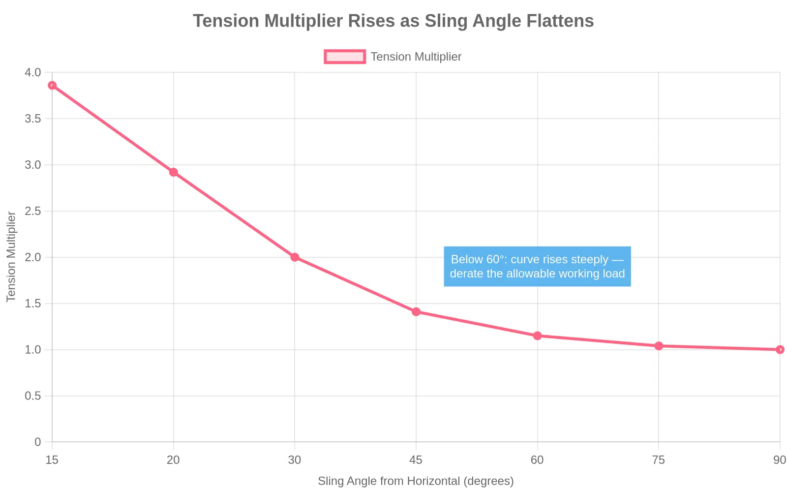
- Sling angles below 45 degrees from horizontal, where the tension multiplier climbs sharply
- Side pull or off-axis loading that bends the hook outside its intended plane
- Dynamic and shock forces from sudden starts, stops, or swinging loads
- Point loading at the hook throat instead of seating in the saddle
- Latch damage or a worn throat opening that shrinks the effective section
These triggers stack. A 45-degree hitch combined with a swinging load can push the true working load far below the nominal rating.
If you run truck-mounted lifting gear as well, give the same scrutiny to checking hook-lift subframes and lift cylinders before a load leaves the ground.
Sling Angle Capacity Derating Reference
The table cross-references sling angle, measured from the horizontal, against the tension multiplier and the effective capacity per leg. The figures assume one sling leg rated at 10,000 lb in a straight vertical pull, so you can scale the percentages to your own hardware.
| Sling Angle (from horizontal) | Tension Multiplier (1 / sin θ) | Effective Capacity per Leg (% of rated) | Effective Capacity per Leg (lb, 10,000 lb rated leg) |
|---|---|---|---|
| 90° (vertical) | 1.000 | 100.0% | 10,000 |
| 60° | 1.155 | 86.6% | 8,660 |
| 45° | 1.414 | 70.7% | 7,071 |
| 30° | 2.000 | 50.0% | 5,000 |
| 0° (approaching horizontal) | approaches infinity | 0% | 0 |
To use the table, find the angle closest to how your leg sits relative to the horizontal. The tension multiplier is how many times the load’s share is amplified in that leg: flatter angle, larger multiplier, more force per leg. The capacity columns show what is left per leg, both as a percentage of the rated vertical capacity and as pounds for a 10,000 lb leg. Moving from 90° to 30° halves the usable capacity and doubles leg tension. Approaching a horizontal (0°) angle drives tension toward infinity, which is why working angles below 30° are avoided entirely.
Factors That Trigger Capacity Derating on a Fork Truck Lifting Hook
A hook’s rated working load limit (WLL) assumes a dead-vertical, perfectly balanced pick. Docks, yards, and job sites rarely deliver that. Use the list below as a pre-lift check: if any item applies, assume capacity derating is in play, and verify your numbers against the load chart before you pick.
- Sling angle deviating from true vertical – The further a leg leans from vertical, the more tension it carries, and a wide angle can cut the assembly’s usable capacity well below the stamped rating.
- Unbalanced multi-leg slings – When legs share a load unevenly, the most heavily loaded leg governs the lift, so derating applies even when the total weight looks comfortable.
- Off-center center of gravity – A load whose CoG sits off the hook’s vertical axis adds bending and side forces the hook was not designed for, shrinking the safe capacity.
- Worn or deformed hook throats – A throat that has stretched, worn, or cracked no longer spreads load smoothly, so derate the hook or pull it from service.
- Attachments added below the hook – Extra shackles, slings, or clamps add weight and leverage, so the whole assembly must be derated for the added gear.
- Dynamic or shock loading – Sudden starts, jerks, and swinging loads multiply static weight by a dynamic factor. Any jarring pick needs aggressive derating.
Before you sign off on a lift, match the load and attachment setup to the equipment so geometry, balance, and hardware stay inside rated limits. When in doubt, derate and reassess. That is cheaper than a dropped load.
Sling Tension Multiplier vs. Sling Angle
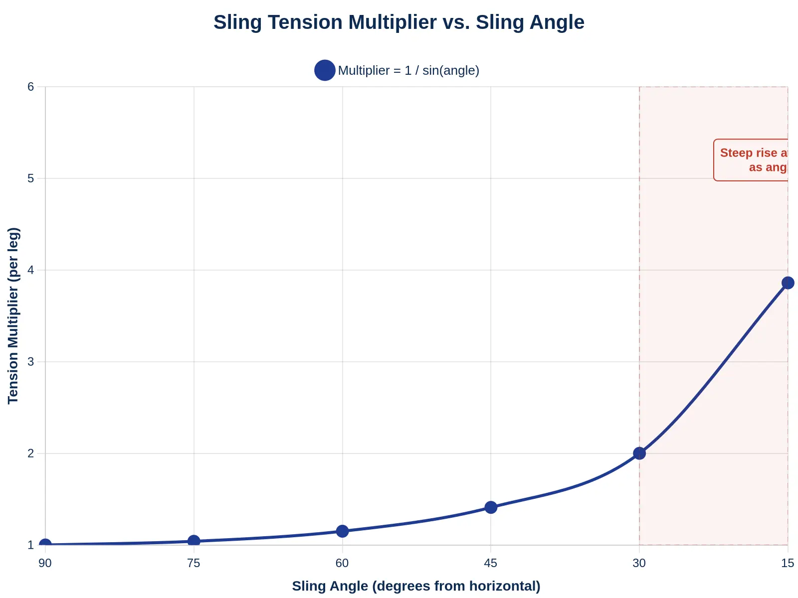
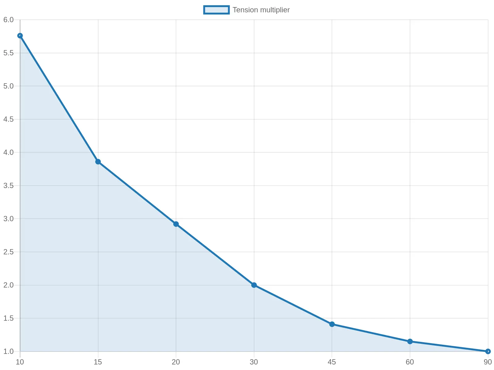
Find your sling angle on the horizontal axis, move up to the curve, and read the multiplier on the vertical axis. The curve stays near 1.0 down to about 45 degrees and climbs steeply below 30, which is how a leg that looked fine at a steeper angle gets overloaded once the hitch flattens.
Sling Angle Limits: The Geometry That Decides a Safe Lift
A fork truck lifting hook can be rated for a generous load while the sling legs, shackles, and pick points beneath it are driven past their limits the moment those legs spread apart. Sling angle limits govern how much tension each leg and connection point actually carries. Ignore the geometry and even a lighter load can exceed the working load limit (WLL).
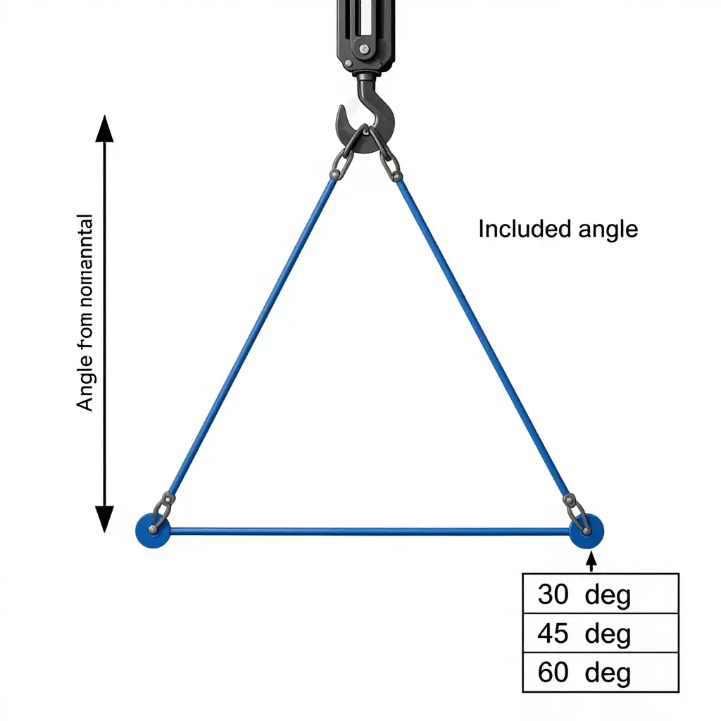
Included Angle vs. Angle From Horizontal
Two conventions describe the same rigging geometry, and confusing them is a classic source of error.
- Included angle is measured at the apex where the two sling legs meet, between the legs themselves.
- Angle from horizontal is measured between each sling leg and the horizontal load line.
The two are complementary: included angle = 180 degrees minus twice the angle from horizontal. A wide, efficient hitch has a large angle from horizontal and a small included angle, so confirm which value your load chart uses before you derate.
The 30, 45, and 60 Degree Benchmarks
Rigging practice uses three angles from horizontal as reference points. As a leg flattens toward horizontal, the tension multiplier (1 divided by the sine of the angle) climbs fast.
| Angle from horizontal | Tension multiplier | Capacity vs. a vertical leg |
|---|---|---|
| 60 degrees | 1.15 | about 87% |
| 45 degrees | 1.41 | about 71% |
| 30 degrees | 2.00 | about 50% |
At 60 degrees the derating is mild. At 30 degrees every leg carries twice its vertical share, and anything flatter should be rejected.
Why Capacity Drops Sharply Below 45 Degrees
A sling supports load only through the vertical load component of its tension. Flatten a leg toward horizontal and that vertical component shrinks while the leg’s total tension grows to make up the difference. Stress rises exponentially: below 45 degrees the multiplier accelerates and the margin between applied tension and the sling’s WLL collapses. That is why 45 degrees from horizontal is the practical floor for most hitches.
Keep Sling Angles Wide
Keep the legs as close to vertical as the load allows. Wider angles hold tension down and relieve the strain on hooks, shackles, and lifting points. If the geometry is tight, lengthen the sling, reposition the pick points, or add a spreader beam instead of accepting a shallow angle.
When to Reject a Rigging Arrangement
Stop the lift and redesign the hitch when any of the following appear:
- Any sling leg is flatter than 45 degrees from horizontal (or the included angle is too large) without an engineered derating.
- The calculated tension, including the multiplier, exceeds the sling’s or hook’s rated WLL.
- The included angle pushes leg tension past the capacity printed on the load chart.
None of this matters if the hardware is not sound, so it pays to verify the lift equipment during routine checks as well. Confirm the angles against the load chart, keep the hitch wide, and a safe lift becomes a calculation you can defend.
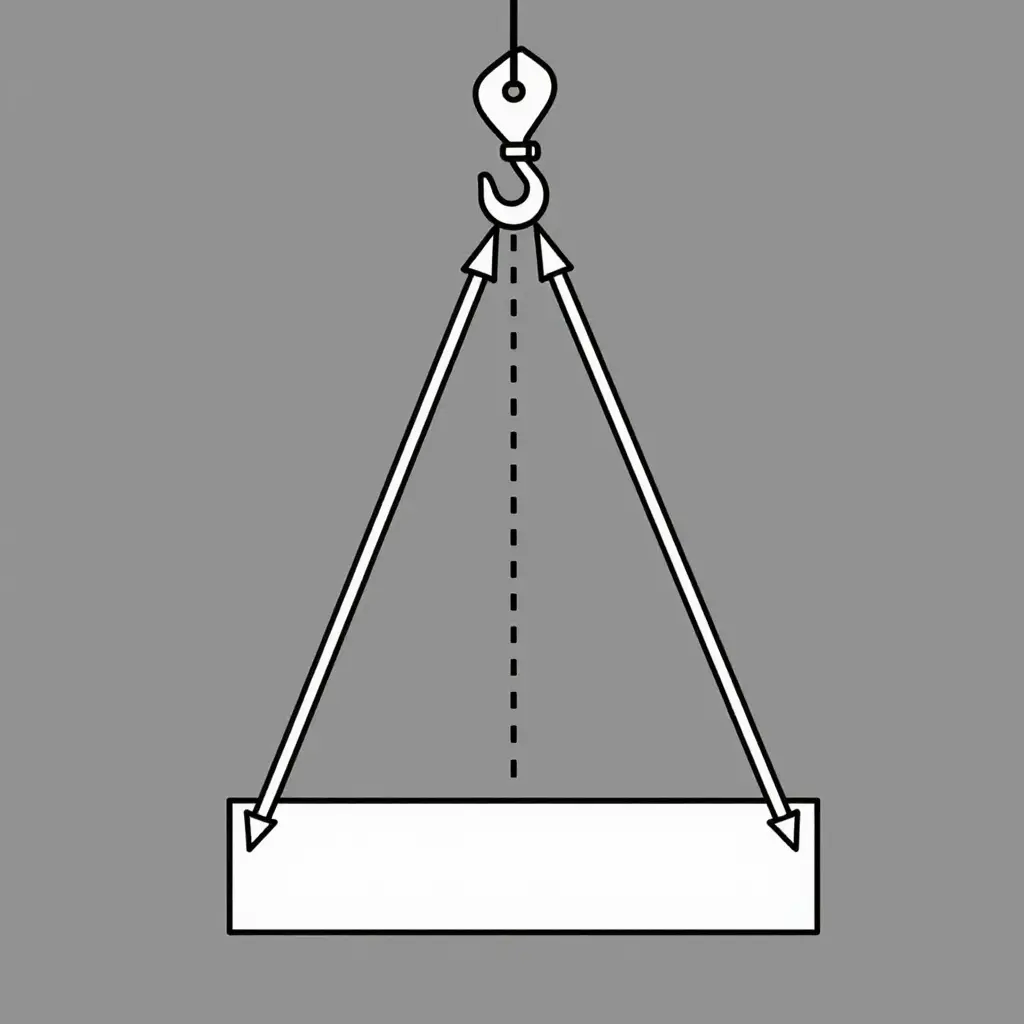
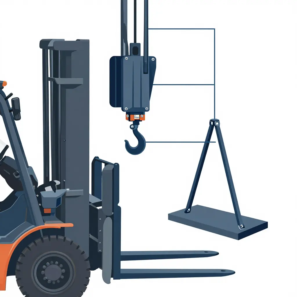
The schematic shows the geometry behind all of this. A single hook at the apex holds two legs splayed at the included angle. Where the legs meet the load, each leg’s tension splits into a vertical component that carries the weight and a horizontal component that squeezes the load inward. Widen the included angle and the horizontal component grows while leg tension rises for the same load. That is why steeper, more vertical legs are always the safer configuration.
How to Read a Fork Truck Lifting Hook Load Chart and Hook Markings
A fork truck lifting hook is only as safe as the numbers on it and the way you read them. Before any lift, check that the load chart and the hook markings match the sling setup actually rigged in front of you.
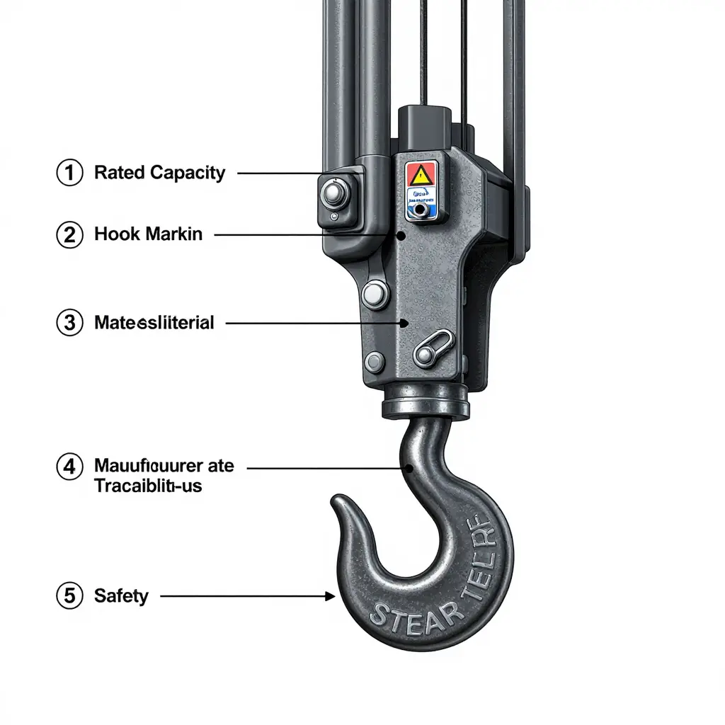
Where rated capacity is stamped
Every hook carries a permanent rated capacity stamp, normally on the body or the load-bearing boss and never on a part you can remove or replace. It should show the working load limit (WLL) in kilograms or pounds, the manufacturer’s name, and a traceability or batch number. A stamp that is missing, illegible, welded over, or hand-punched makes the hook unserviceable.
Identifying hook class and material
The designation line tells you what the hook is made of and how it is rated. Its hook identification code, required by ASME B30.10, indicates the material classification, such as carbon steel, alloy steel, or stainless, along with the fatigue and proof-load characteristics that go with it. It also distinguishes a forged hook, which takes higher duty and resists fatigue better, from a limited-duty cast or welded design.
How the chart changes with sling configuration
A load chart is written for one specific sling configuration and sling angle. Drop the angle between the sling legs and the horizontal and tension rises sharply in each leg, so the capacity available to the assembly falls.
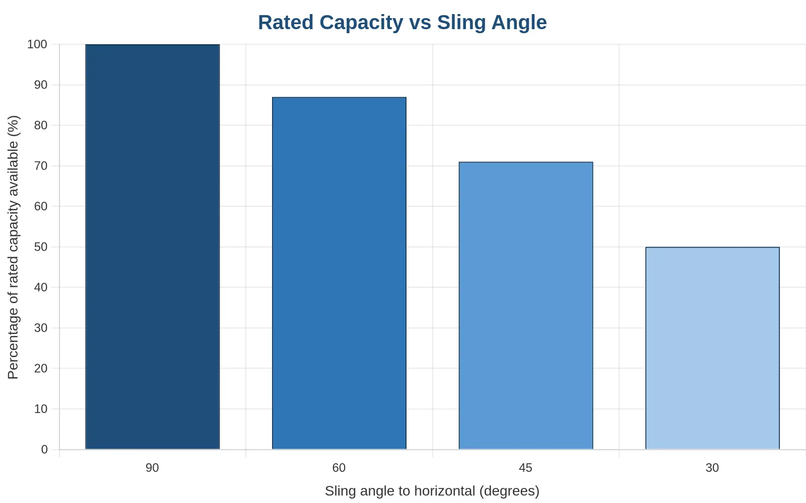
| Sling angle to horizontal | Capacity available |
|---|---|
| 90 degrees | 100% |
| 60 degrees | 87% |
| 45 degrees | 71% |
| 30 degrees | 50% |
Common misreadings that lead to overload
- Reading the two-leg chart value while lifting with four legs at a shallow angle.
- Using the hook’s rated capacity directly without applying the angle derating factor.
- Ignoring the weight and angle of the below-the-hook attachment itself.
- Trusting the planned angle instead of the measured one.
Match the chart value to the sling angle you measure on site, not the one you assumed. If fleet capacity is part of that review, see our guidance on matching equipment capacity to the load.
When Load Sharing Goes Uneven: Multi-Leg and Off-Center Derating
A multi-leg sling looks balanced. That balance is an assumption, and a dangerous one. A fork truck lifting hook rarely sits directly above the center of gravity (CG) of the load, and the load itself is rarely symmetrical. The result is uneven load share, and the most dangerous shortcut in any lift plan is the belief that every leg carries an equal fraction of the weight.
The center of gravity decides the load share
The center of gravity is the point where the load’s weight effectively acts. When it sits directly beneath the hook and between the leg attachment points, a two-leg sling gives each leg roughly 50% of the load. Shift the CG toward one leg and that leg’s share grows while the other unloads. With a four-leg sling, the accepted convention is that only the two legs sharing the CG should be assumed to carry the load, roughly 50% each, not 25%. That is a built-in derating factor grounded in rigging practice, not a design flaw.
Uneven distribution raises tension in the worst leg
Assume equal sharing and you size every leg to a small fraction of the load. In reality the most heavily loaded leg carries more, sometimes far more, and that one leg governs whether the entire lift is safe. The tension multiplier converts the total load into the force that worst-case leg actually carries, and it grows sharply as the sling angle flattens.
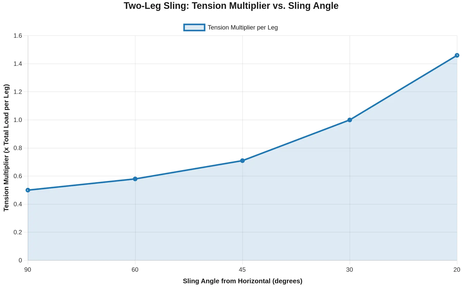
| Sling angle from horizontal | Tension multiplier (2-leg) | Load per leg on a 10,000 lb load |
|---|---|---|
| 90 degrees | 0.50 | 5,000 lb |
| 60 degrees | 0.58 | 5,770 lb |
| 45 degrees | 0.71 | 7,070 lb |
| 30 degrees | 1.00 | 10,000 lb |
| 20 degrees | 1.46 | 14,620 lb |
Apply the tension multiplier to the worst-case leg
- Determine the CG position relative to the hook and the leg attachment points.
- Identify which legs actually share the load (for four-leg slings, usually two).
- Measure the sling angle of the worst leg from horizontal.
- Multiply that leg’s load share by the tension multiplier for its angle.
- Compare the result against the leg’s rated capacity after all capacity derating for wear, D/d ratio, and configuration.
Only then does the whole-assembly rating make sense: a leg rated for 5,000 lb may legally carry just 2,500 lb once angle and configuration are applied. Confirm hardware ratings through verified subframe and lift cylinder checks before you trust any chart.
Why assuming equal sharing is unsafe
Equal-sharing math understates the tension in the critical leg, which inflates the apparent safety margin. A sling that calculates as fine can fail because one leg was doing most of the work. Sizing to the worst-case leg is the only defensible method, and it is the foundation of every reputable load chart.
Selecting and Matching the Hook and Below-the-Hook Attachment to the Lift
A lifting hook is never a standalone device. Hang a sling, a spreader beam, or a custom fixture on it and you have a new assembly whose working load limit (WLL) is set by the weakest component and the geometry of the connection. Matching the hook and its below-the-hook attachments to the specific lift is not a paperwork exercise. It is the decision that separates a safe lift from a failure.
Four factors interact, and a mismatch in any one of them decides the outcome:
- Hook capacity – the hook’s rated WLL applies only when the load hangs vertically from the saddle. Off-axis loading, a twisted or side-loaded hook, and worn throats all reduce that number before a single sling is tensioned.
- Sling angle – as the angle between the sling legs and the horizontal drops, tension in each leg climbs fast. Two legs at 90 degrees share the load evenly at a factor of 1.000, but flatten them to 30 degrees and each leg now carries twice its share.
- Attachment geometry – the span, hook-to-load distance, and pick-point positions on a spreader or fixture set the load vector applied to the hook.
- Load weight – the true, rigged weight, including the below-the-hook attachments themselves, is the starting number everything else is calculated from.
When those four line up, the hook and attachment share the load exactly as the load chart intends. When they do not, the weakest link shows up at the worst possible moment.
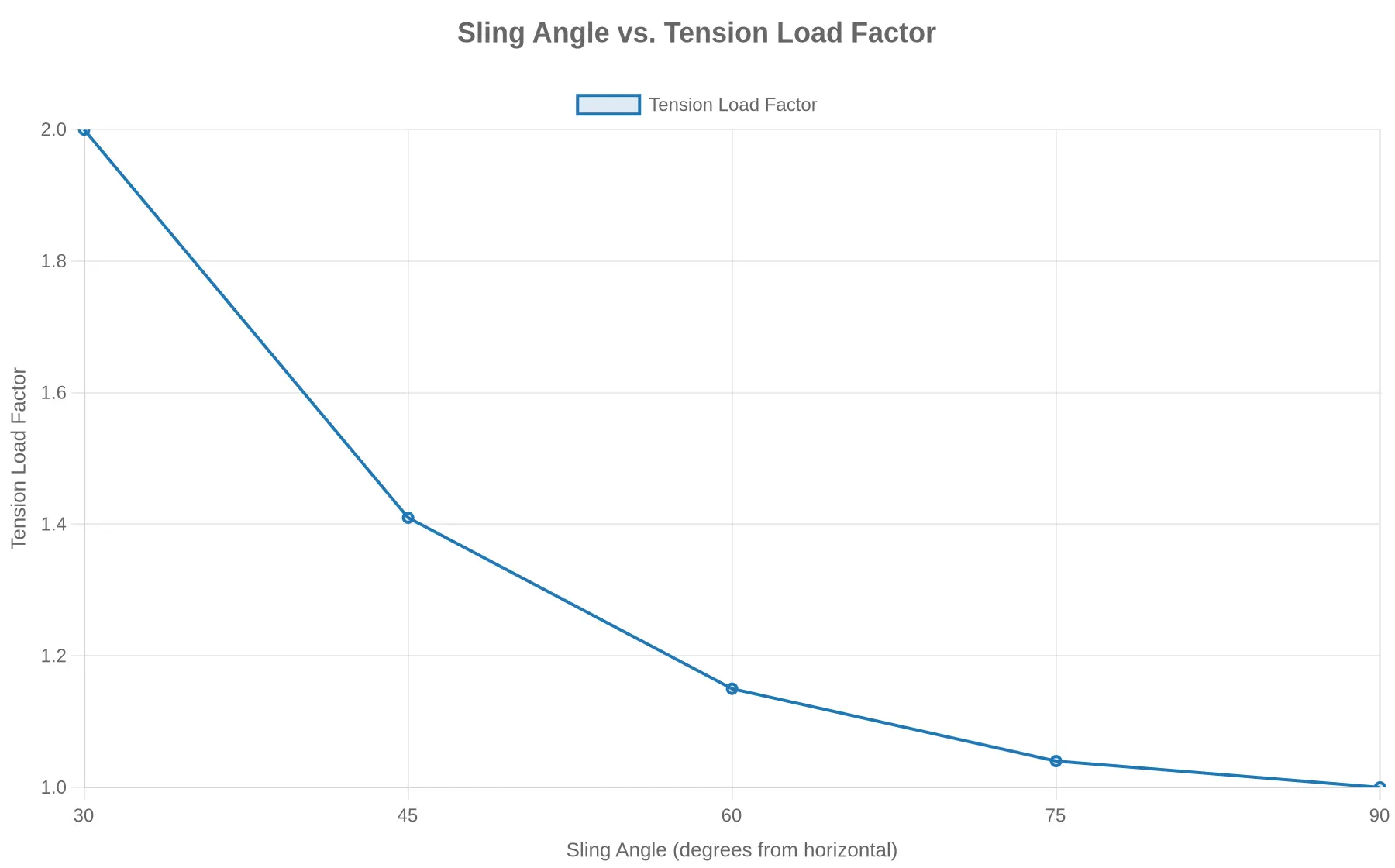
Reading the derating curve
| Sling angle (to horizontal) | Tension load factor | Tension per leg (2,000 lb load, 2 legs) |
|---|---|---|
| 90 degrees | 1.000 | 1,000 lb |
| 60 degrees | 1.155 | 1,155 lb |
| 45 degrees | 1.414 | 1,414 lb |
| 30 degrees | 2.000 | 2,000 lb |
A pair of slings rated at 2,000 lb each can look compatible with a 45-degree hitch until you run the numbers and find each leg pulling 1,414 lb, with a shock-load margin barely inside the chart. Tighten the angle to 30 degrees and each leg carries the full 2,000 lb, with nothing left for shock. The pick points and the hook above them still have to be rated for the whole load, and that mismatch is what decides the lift.
The same discipline governs hooklift and special vehicle work, where the hook must be sized to both the container and the chassis. The mechanics behind matching bin size to chassis length keep the cycled load inside the hook’s rated envelope, while weighing hooklift versus cable hoist helps you pick the attachment logic that fits a tight city block. Before any of it lifts a load, the subframe and lift cylinder checks confirm the vehicle can take the repeated stress. Either way the rule is the same: match hook capacity, sling angle, attachment geometry, and true load weight, or knowingly accept a lift that is not safe.
Conclusion and Safe Lift Decision Framework
Three variables decide whether a lift succeeds or fails: the derated capacity of the fork truck lifting hook, the geometry of your sling angles, and whether you read the load chart for the exact configuration in front of you. Each is simple in isolation, yet they compound. The hook can be rated well above the load while a shallow sling angle overloads the legs and pick points beneath it, and a chart read against the wrong hitch erases the safety margin you thought you had.
Capacity derating is not a formality. It is the bridge between a catalog number and real-world conditions. Off-center picks, dynamic starts, worn hardware, and sling angles below 45 degrees all reduce the load any hook can legally carry. Sling angle limits behave the same way: as the angle from horizontal falls, tension in each leg climbs sharply, so a 30-degree pick can double the force on a sling that looked perfectly adequate on paper.
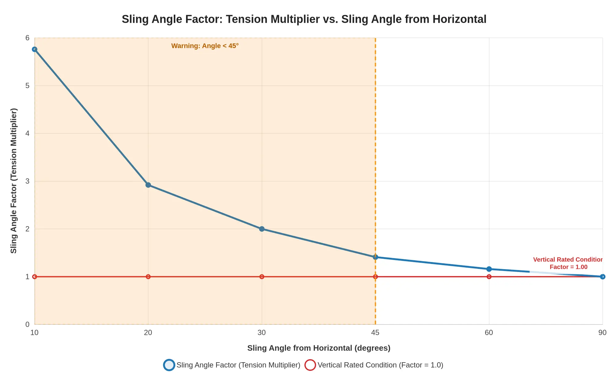
Load charts capture these relationships, but only if you interpret them for the actual hitch and attachment geometry.
Pre-Lift Decision Framework
Work through this sequence before every lift, without exception:
- Verify the hook rating. Confirm the fork truck lifting hook’s rated capacity and its inspection record, and check that no unauthorized repair or modification has altered its rating.
- Establish the true load weight. Add the weight of slings, shackles, spreader beams, and any below-the-hook hardware to the payload.
- Apply capacity derating. Reduce the rated capacity for duty cycle, dynamic loading, off-center picks, and environmental factors such as heat or wind.
- Measure and confirm sling geometry. Record the angle from horizontal; if it falls below 45 degrees, recalculate tension or reconfigure the rigging.
- Interpret the load chart correctly. Select the row and column matching your actual hitch and configuration, never interpolate from memory.
- Account for uneven loading. Verify that the center of gravity sits within the rated footprint and that no single leg carries a disproportionate share.
- Decide and document. Proceed only when every value clears its limit; otherwise stop, reduce the load, or re-rig.
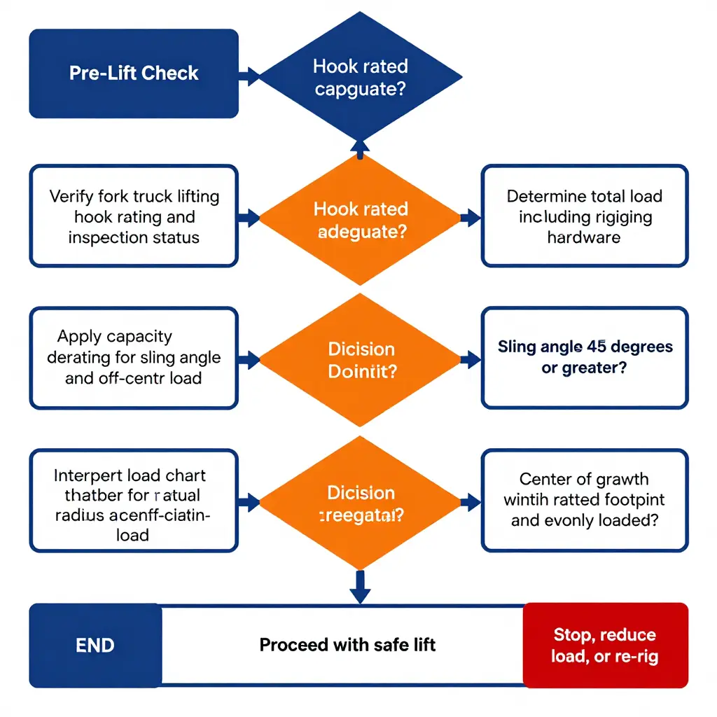
Pairing this discipline with matching lifting capacity to the load it actually moves keeps the whole sequence grounded in evidence rather than assumption.
Why Derating and Sling Angle Limits Decide a Safe Lift
No single number makes a lift safe. The derated capacity of the hook and the tension forced by sling angle limits are the two factors that decide whether a pick is safe. Ignore either one and a compliant-looking lift becomes an overload waiting to happen. When you verify ratings, respect sling-angle physics, and read the load chart for the real condition, you replace assumptions with evidence. A safe lift then rests on something you can point to.