Diagnostic Framing: A Stalled Cart Tipper Is Usually a Flow Problem
A cart tipper that lifts a bin partway and stops is usually short of oil flow, not short of force. The lift cylinder can still make full pressure; what it cannot get is enough volume, or a clear enough return path, to finish the stroke. In hydraulic terms the symptom falls into one of three patterns. The rod stalls under load with no relief-valve chatter, which rules out a pressure limit. The rod stalls at the same point in every stroke, which points to a mechanical restriction, a wrong split at the divider, or a porting and hose-sizing problem. Or bins stop halfway only when two tippers are operated together, which means the divider is not allocating flow as intended. Each pattern is a flow signature, and each one is read at the flow divider before any other component is touched.
Order matters as much as method. Starting at the cylinder (resealing it, replacing the rod, swapping the control valve) burns labor hours and parts budget before the restriction is located, and it often hides the fault for a few cycles, because disturbed lines and refitted fittings change flow behavior just long enough to look like a repair. A failure that stops bins halfway instead of refusing to lift them is proportional, and proportional failures point upstream. The flow divider splits pump output between circuits, or between tipper functions run at the same time; a worn spool, a stuck compensator, or a mis-set split ratio starves the tipper circuit exactly where demand rises.
The sequence below does not change: flow divider first, then relief and pump, then cylinder and linkage. Work the steps in that order, record measured flow and pressure at each stage, and condemn a component only when the numbers support it. Where delivery volume is the suspect, the same reasoning that explains why cold-morning lifts stall on hydraulic lift systems applies, since restricted flow at low temperature behaves much like a worn divider.
Cart Tipper Circuit and Flow Divider: How the Hydraulic Layout Actually Works
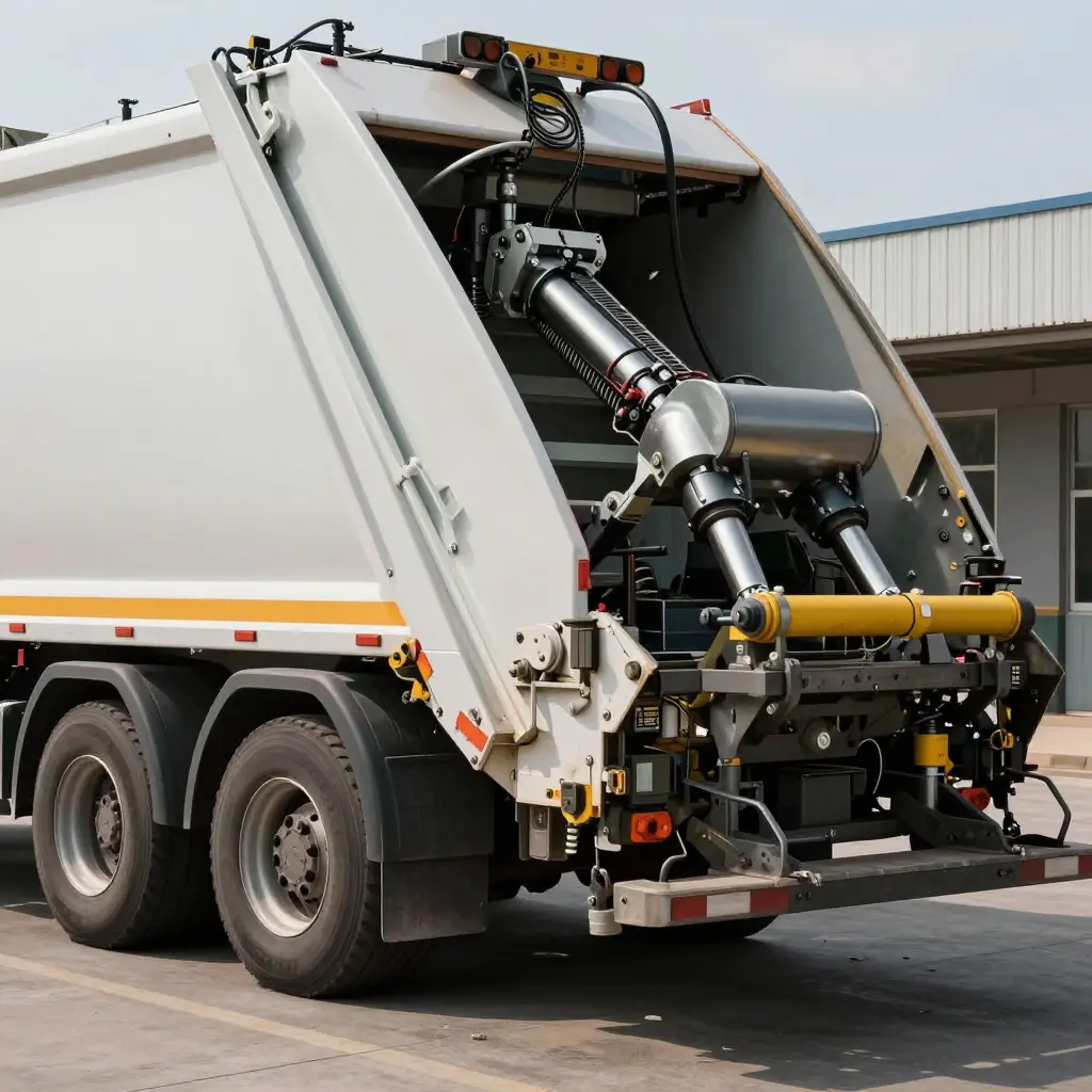
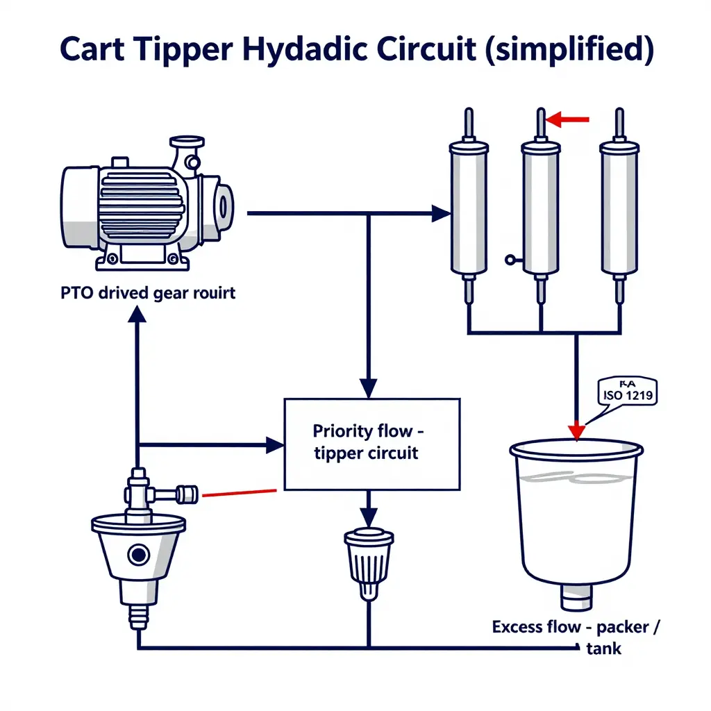
A cart tipper hydraulic system on a refuse truck is a short circuit: pump, relief valve, flow divider, one or two directional control valves, and the lift cylinders, with oil returning through a filter to the tank. Few components, and very little room to hide a fault. Once the layout is clear in your head, a bin that quits halfway turns into a flow question instead of a guessing game.
The layout, pump to cylinder
- Pump output. A PTO-driven, fixed-displacement gear pump supplies the tipper circuit, often with a dedicated section or a tee off the main work line. Flow is proportional to engine or PTO speed, so shop testing at idle tells you very little. Check flow at working rpm.
- Main relief valve. Mounted downstream of the pump and upstream of everything else, it caps system pressure. Check it hot, with a gauge on the pressure line, and confirm the setting against the OEM spec before blaming anything downstream. A relief that opens early flattens every function on the truck, not just the tipper.
- Flow divider. Takes total pump flow and splits it, either between two tipper circuits or between tipper demand and packer demand. This is the component to check first when only one side of the tipper misbehaves.
- Directional control valves. Solenoid or manual spool valves, one per tipper station, usually with load-holding checks or pilot-operated checks so a loaded bin cannot creep down when the valve centres.
- Tipper lift cylinders. Single- or double-acting, one or two per station. Two-cylinder tippers need matched displacement, not just matched pressure, or the mast racks and binds partway through the stroke.
- Return path and filtration. Oil leaves the cylinders and valve bodies, passes through the return filter (and cooler, where fitted), and drops back to the reservoir. A loaded return filter is a real restriction: it raises back pressure, slows rod retraction, and once the element goes into bypass it sends unfiltered oil straight back to the tank.
What a flow divider actually does
A flow divider splits flow; it does not build or equalise pressure. It holds its split even when the two legs see very different loads, which is the property that makes it useful and the one that fails quietly.
- Displacement split ratio. In a gear-type rotary divider, two gear sections share a common shaft, and the ratio of their displacements (50/50, 60/40, and so on) sets the split. A 60/40 unit sends 60 percent of inlet flow to the primary port regardless of which leg is carrying the heavier load.
- Priority flow. A spool-type divider (priority valve) with a pressure-compensated spool holds a fixed priority flow to the tipper leg and dumps the remainder to the secondary leg or to tank. On a truck where the packer cycles while the tipper works, this is what keeps tipper speed consistent.
- Proportional splitting. Some layouts use a proportional divider to feed two tipper stations in a fixed ratio, rather than protecting one at the expense of the other.
- Pressure compensation. The compensating spool or the gear geometry absorbs the pressure difference between legs: flow stays put while pressure floats.
| Divider type | How it splits | Typical weak point |
|---|---|---|
| Gear-type rotary | Fixed ratio set by gear displacement | Internal leakage past worn gear tips and end plates |
| Spool-type priority | Fixed priority flow, remainder to secondary | Sticking or scored compensating spool, clogged sense orifice |
| Proportional (spool) | Fixed ratio across two work legs | Contamination holding the spool off-centre |
Why a worn or sticking divider starves one cylinder
Internal leakage is the failure mode that matters. As a gear divider wears, oil slips past the gear tips and end plates and crosses from the high-pressure leg to the low-pressure leg, or straight to the return gallery. The unit still looks fine and still passes a no-load test, but under load it hands one cylinder less than its share of flow.
A sticking compensating spool does the same thing more abruptly: it parks in one position, the split ratio drifts, and one leg runs rich while the other runs lean. With compensation that can no longer respond, the imbalance becomes load-dependent, which is why the symptom appears only once the bin is up and the cylinder load has built.
Where the bin stops tells you which of the two you are chasing:
- Bins stop halfway through the stroke. Flow starvation. The starved cylinder moves slower than its twin, the linkage racks, friction climbs, and travel dies partway up. Relief pressure is usually not reached.
- Bins stall at the top. A pressure event: relief opening early, a mechanical bind, or a cylinder that bypasses internally once it reaches full extension.
Meter both legs at the tipper outlets and compare them with the nameplate split ratio. If the pump is delivering rated flow and the relief is set correctly, one lagging cylinder is the divider’s fault. A divider that cannot hold its ratio cold and hot, or that shifts ratio when the packer is cycled, is worn internally and should be replaced rather than shimmed.
One more thing on the return side: a restricted filter will not stop a bin halfway by itself, but it exaggerates every divider fault by raising back pressure and thinning the flow margin. Change the return element and check for suction-side air ingress before you condemn the divider. And if the tipper shares its circuit with the body, a tired packer can make a healthy divider look bad, because the same flow-sharing logic turns up in rear-load compactor packer blade issues that only show up when two functions run together.

How to read the schematic
The drawing leaves out hardware so the plumbing carries the message. Heavy lines are pressure, light lines are return and drain, and every arrowhead marks the direction the oil actually travels.
- Left of the diagram: reservoir, pump, and the spring-loaded relief valve sitting on the pressure line with its own drain back to tank. Anything downstream of that valve only ever sees oil the relief has already agreed to pass.
- Center of the diagram: the flow divider. It sits downstream of the relief valve and upstream of both directional control valves, and it has no operator input and no selector spool of its own. Its only job is to divide pump output between the two branches.
- Right of the diagram: two branches, each with its own directional control valve and its own double-acting lift cylinder. Each branch is fed from a separate divider outlet, so a fault on one side does not automatically disable the other.
- Bottom of the diagram: the return path. Oil from both cylinders and both valve bodies merges, passes through the filter, and drops back to tank. The filter sits on the shared leg rather than on a single branch because a restricted element raises return-line pressure and makes both tippers lazy.
Read in that order, the schematic explains the classic halfway-stall complaint: if a bin rises part way and stops while the pump still sounds loaded, the restriction or internal leakage is usually in the shared supply, not in the cylinder. For more on how flow loss and cold oil stall hydraulics, see our notes on why cold morning lifts stall.
Diagnostic Procedure for a Cart Tipper Where Bins Stop Halfway
Work the steps in order. Steps 3 through 6 exist to prove or eliminate the flow divider before anyone touches the relief valve or pulls a cylinder. Take every reading with the oil at normal operating temperature (50 to 60 °C / 120 to 140 °F), the PTO engaged, and engine speed at the published test rpm. Write each number on a worksheet rather than keeping it in your head; you will be comparing readings against each other later.
-
Confirm the symptom and document the stall position. Raise a known-weight bin and watch for the point of arrest. Measure the stall angle with a digital inclinometer on the lift arm, exposed rod length with a tape measure, and fluid temperature at the reservoir with an infrared thermometer. Pass: the arm travels the full stroke to the dump angle and returns within the cycle time published for that model. Fail: a repeatable stop at the same mid-stroke point, or a stall point that moves as oil temperature rises.
-
Check reservoir level and suction strainer. Read level on the sight gauge after cycling the circuit, take fluid temperature at the tank wall with an infrared thermometer, and inspect the suction strainer for fines and rag. Where a test port exists, read suction vacuum with a compound gauge. Pass: level inside the hot-running band, clean strainer, suction vacuum below roughly 17 kPa (5 inHg). Fail: low level, a loaded or torn strainer, or vacuum above 17 kPa, which points to aeration and cavitation upstream of the pump.
-
Measure pump flow and pressure at the inlet of the flow divider. Tee an inline turbine or gear flow meter (sized to the circuit, typically 5 to 100 L/min) into the pressure line feeding the divider inlet and fit a 0 to 350 bar pressure gauge at the same point. Pass: flow within ±10 % of rated pump output at test rpm, with inlet pressure at least 20 bar below the relief setting. Fail: a flow shortfall, or inlet pressure riding at or near relief, which points to a downstream restriction. Note whether the shortfall appears only with cold, thick oil.
-
Measure flow at each divider outlet, no load and loaded. Move the flow meter to each outlet in turn, no-load first, then repeat with ballast equal to a typical commercial bin. Hold a pressure gauge on the loaded line and log temperature on both legs. Pass: flow under load stays within ±5 % of its no-load reading, with no pressure spike at the divider body. Fail: an outlet that loses flow or spikes in pressure under load while the other leg stays steady.
-
Compare each outlet reading against the published split ratio. Divide outlet flow by inlet flow and compare the percentage with the manufacturer’s split specification for the cart tipper circuit. Pass: each leg within ±5 % of its published share. Fail: a leg biased low under load, which confirms the divider as the fault and justifies opening it instead of moving on.
-
Inspect the flow divider for contamination, spool sticking, and seal bypass. Bench or field-strip the divider, inspect the spool and bore for scoring, measure spool-to-bore clearance with a micrometer, patch-test the oil for particulate count, and pressure-test each seal path. Pass: free spool travel by hand, no visible scoring, clearance within the OEM service limit, and bypass leakage below the specified value at working pressure. Fail: lapped surfaces marked, a spool that hangs, or measurable internal bypass past the seals.
-
Only now, test the relief valve setting. Tee a gauge into the circuit, deadhead the outlet against a hard stop, and bring pressure up slowly until the valve cracks. Pass: the valve cracks and reseats within ±5 % of the nameplate setting, with no creep while held. Fail: a setting that has drifted low (premature stall) or high (upstream damage risk).
-
Test cylinder internal leakage. Extend the rod to full stroke, hold it under load with the pressure gauge on the bore end and the line capped, and read rod drift over five minutes. Pass: drift within the OEM allowance and no drop in held pressure. Fail: pressure decay with steady rod movement, which means piston seal bypass. If the rod or gland is suspect, review the lift cylinder checks before ordering parts.
-
Check hose internal collapse and linkage geometry. Run a flow meter across each suspect hose section and scan the same lines with an infrared thermometer to find a cold-then-hot pinch point. Check pivot pin wear, arm angle, and cylinder mount squareness with a tape measure and angle finder. Pass: full flow across every hose with even temperature, and linkage angles matching the OEM drawing. Fail: flow loss across a hose that vanishes when it is straightened (inner liner collapse), or geometry binding the arm before full stroke.
-
Loaded re-test and sign-off. Reinstall everything, cycle at least ten full bin lifts at working weight, and log flow, pressure, temperature, and cycle time on every pass. Pass: no stall, cycle times within spec, and stable temperatures with no creep in readings across the ten cycles. Fail: any recurrence of bins stopping halfway, which sends you back to step 3 with the recorded data.
Diagnostic Matrix: Cart Tipper Stalls at Half Stroke
The rows are ordered by likelihood. Flow divider faults sit at the top because they account for the largest share of mid-stroke stalls, and because the divider has to be cleared before relief, pump, or cylinder checks mean anything. Readings assume a 50/50 divider unless the OEM schematic states otherwise; treat a deviation beyond ±5% of nominal split as diagnostic. Cold-start stalls can mimic a divider fault, so confirm the fault repeats at operating temperature before condemning parts; a look at why hydraulic lifts stall on cold mornings helps separate temperature-driven viscosity effects from a genuine divider restriction.
| Observed symptom | Most probable root cause | Quick field test | Corrective action |
|---|---|---|---|
| Uneven or weak lift on one side only | Flow divider spool sticking or scored; uneven split | Flow meter on both work ports at 1500 rpm; compare L/R flow (target 50/50, ±5%) | Pull and clean spool; replace flow divider cartridge |
| Stall at mid-stroke with both tippers operated | Divider fault plus priority logic starving second circuit | Tee gauges at both cylinders; both pressures collapsing at mid-stroke, to 1500 psi or below | Replace flow divider; verify port plumbing against schematic |
| Slow lift at low engine rpm | Divider under-compensating below pump flow threshold | Tach 900 rpm vs 1800 rpm; time full cycle, compare ratio | Reseal/replace pressure compensator; check pump displacement setting |
| Stall with relief valve noise | Relief cracking early; divider holding oil back | Inlet gauge; relief opening below spec (e.g. 2500 psi vs 3000 psi) | Reset relief to OEM spec; inspect divider spool for scoring |
| Drift-down after stalling | Internal leakage at divider spool or cylinder seals | Load-hold 5 min; measure rod creep >3 mm/min | Reseal cylinders; replace divider; test pilot check valve |
| Stall that appears only with heavy bins | Relief setting marginal; divider bypass leaking under load | Load bin to rated kg; pressure gauge vs spec at 100% load | Adjust relief to spec; replace worn divider; confirm cylinder bore/rod size |
| Stall that disappears at high pump speed | Restriction upstream of divider; low-speed flow starvation | Compare 1000 rpm vs 1600 rpm; flow delta >20% flags restriction | Relocate divider upstream of restriction; upsize line; replace kinked hose |
Reading the Matrix Correctly
Two rows naming the same component, say uneven lift plus a mid-stroke stall with both circuits loaded, justify replacing the divider rather than resealing it. A single row pointing at relief or pump output needs gauge confirmation before any adjustment, since an over-adjusted relief can mask a divider that is already bypassing internally.
Reading the Evidence: Measured Outlet Flow vs Specification
Before you pick up a wrench you need one clean data point: actual flow at each divider outlet, measured against the published split ratio. Until that number exists, the rest of a halfway-bin diagnosis is opinion.
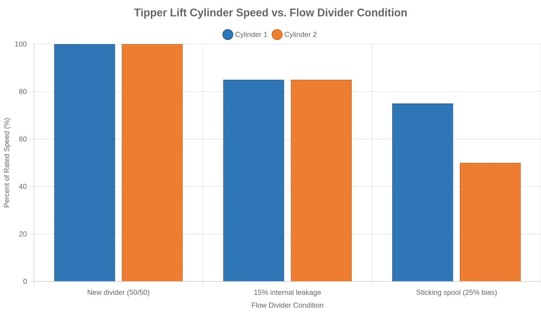
The chart below shows the classic two-port failure. Rated supply is 20 L/min and the spec is a 50/50 split, so each outlet should carry 10 L/min. Outlet A reads 10.2 L/min. Outlet B delivers 7.8 L/min, a 22% shortfall against spec. Together the two outlets account for 18 L/min, so supply is also 2 L/min below rating; that is a second finding, not a rounding error.
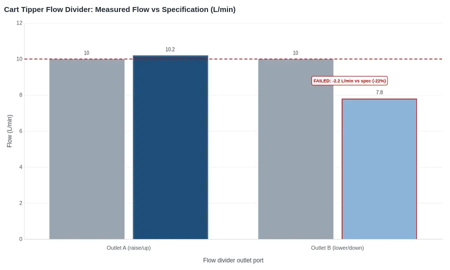
Why that 2.2 L/min gap stops the bin at half stroke
The divider meters equal volume to each side of the circuit so the two cylinders travel together. When one outlet is starved, that cylinder lags. The bin keeps rising until the leading cylinder, the healthy one, runs out of stroke; then the circuit deadheads and the bin stops wherever the lagging cylinder left it. In practice that is roughly mid-stroke, with the bin sitting at an angle and the pump labouring against relief.
So the symptom looks mechanical (bent arm, seized pin, twisted bin) while the cause is volumetric. Bins stopping halfway rather than at the top is a flow fault, and the divider is first in the queue.
The numbers, side by side
| Outlet port | Specification (L/min) | Measured (L/min) | Deviation | Result |
|---|---|---|---|---|
| Outlet A – raise/up | 10.0 | 10.2 | +0.2 (+2%) | Pass |
| Outlet B – lower/down | 10.0 | 7.8 | -2.2 (-22%) | Fail |
| Total supply (pump) | 20.0 | 18.0 | -2.0 | Marginal |
Two things in that table matter. Outlet A reading slightly high is normal; a worn divider often bleeds a little extra to the free-flowing side. And the total is 2 L/min down, which tells you to check supply before condemning the divider itself.
How to take the measurement so the chart means something
- Get the oil to working temperature. Cold 46-weight oil will under-read on both outlets and send you chasing a fault that disappears by lunchtime. If your failures are cold-morning only, work through hydraulic stall and flow-starvation checks on cold starts before anything else.
- Test at the divider outlets, not at the cylinder ports. Cylinder-end readings include line losses and internal bypass, and they smear the result.
- Use a flow meter whose pressure rating sits above the circuit’s relief setting, with the oil at operating temperature, and record flow under the same load condition for both ports.
- Record both numbers against spec, not against each other. A 50/50 divider reading 8.0 and 8.0 is balanced but still starved: both bins will be slow, and neither will reach the top with authority.
- Check relief and pump delivery before replacing the divider. A failing pump produces two low readings, not one.
What the pattern tells you
- One low, one on spec: the divider is internally worn or one spool is sticking. Rebuild or replace.
- Both low, equal: supply problem, whether pump wear, relief lifting early, a restricted suction, or a clogged return filter.
- Both correct, bin still stops: move downstream to cylinder internal bypass, a bent rod, or a mechanical bind in the arm. The divider has done its job.
A measured number sitting next to the specification ends the argument. Show the failed bar to a driver, a supervisor, or a warranty department and the conversation goes straight to the repair order.
Flow Divider Failure Modes: What Fails, What Proves It, and What Fixes It
On a cart tipper, the flow divider splits pump output between the lift and tilt/return circuits so both functions move at a controlled, predictable rate. When a section leaks, sticks, or bypasses internally, pump volume takes the path of least resistance and the lift function feels it first. Every mode below has a measurement that proves it, so the job comes down to matching a symptom to a reading rather than swapping parts until the bin moves again.
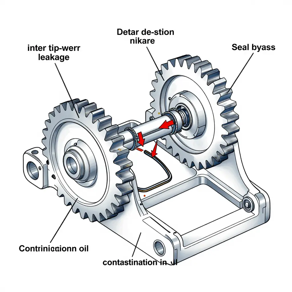
The six failure modes you will actually find
- Rotary gear divider wear and internal leakage between sections. Gear tips, end plates, and bores wear until oil crosses from the high-pressure section to the low-pressure section. Measurement: a section-to-section leakage test with the outlet capped and the unit at rated pressure, plus a flow-meter check at each outlet at operating temperature. Leakage above the OEM limit, or flow falling off sharply once the oil is hot, condemns it. Correction: rebuild with new gears and plates, or replace the divider as a unit.
- Spool-type divider sticking from varnish or debris. The symptom is jerky, delayed, or uneven sequencing: one function moves only after pressure spikes. Measurement: gauges on each outlet to catch a delayed pressure rise, then a manual spool-freedom check at teardown with the bore inspected for gum and varnish. Correction: solvent-clean or replace the spool, flush the circuit, and fix the oil overheating that created the varnish in the first place.
- Seal and O-ring bypass. External weeping is easy to spot; internal bypass is not. Measurement: case-drain flow against spec and a pressure-hold decay test with the cylinders blocked. Correction: reseal with the correct compound, and check for extrusion and excessive case backpressure.
- Cracked or scored divider housings. Measurement: visual and dye-penetrant inspection, bore scoring checked with an internal micrometer, and a repeat leakage test that fails immediately after a fresh reseal. Correction: replace the housing or the whole unit, and investigate aeration and mount stress as the root cause.
- Incorrect replacement divider with the wrong split ratio. Measurement: confirm the tag and part number against the OEM bill of material, then verify the actual ratio with a flow meter at each outlet at rated engine rpm. Correction: install the correctly rated unit.
- Contamination introduced during service. Grit from an open port or a dirty bench wipes out a fresh divider. Measurement: patch test or particle count on an oil sample, cut open the return filter, and look for debris in the spool bores. Correction: flush the circuit, fit new filters, and cap every port during the repair.
Why the wrong divider comes back
A divider with the wrong split ratio is not a "close enough" part. If the lift section is undersized it starves the lift cylinder from the first cycle, and the same half-lift complaint is back within days. The mechanic assumes the new divider failed, replaces it again, and never finds the fault, because the overheating and elevated leakage caused by running the unit outside its design ratio get blamed on the part rather than on the specification. Verify the ratio on the bench before installation, not after.
Back to the bin that stops halfway
A bin that rises partway and hangs is a flow-starvation symptom, not a cylinder symptom. The divider is the first component to test because it sits between a healthy pump and every downstream function. Prove each mode with the measurement above, fix that specific fault, and the lift cycle comes back to a full stroke. For more on how oil condition and temperature change divider behavior, see these cold-weather hydraulic stall diagnostics. A verified divider in a clean garbage truck hydraulic system finishes the stroke; a marginal one leaves operators hand-lifting bins all route long.
Causes to Exclude After the Flow Divider Passes
Once the flow divider splits flow evenly and holds its ratio under load, typically within about 10 percent of the rated split and with no drop-off when the tipper circuit is deadheaded, the divider itself is no longer the prime suspect. From that point the diagnostic order moves downstream: to the relief, the cylinder, the plumbing, the pump drive, the mechanics of the arms, and finally the bin. Be clear on one point before starting: these checks come after the divider, not instead of it. Skipping the divider test and chasing a pump or a relief spring is the most common reason a cart tipper gets two or three parts thrown at it and still stalls halfway up.
With the divider verified, work through the following, each with a measurable reading to confirm or clear it:
- Relief valve set too low or leaking. Tee a gauge into the lift circuit and deadhead the cylinder against a hard stop. Expect the relief to crack at the manufacturer’s setting (commonly 2,500-2,900 psi on cart tipper circuits) and hold that pressure steady for 30 seconds. A valve that cracks 200-300 psi early, or creeps downward while held, is passing oil and will stall a bin exactly at mid-stroke where load peaks.
- Cylinder piston seal bypass. Extend the lift fully, hold it under a rated bin, and watch rod position with the engine off. Expect less than about 3 mm (1/8 in) of drift per minute and full held pressure with no internal transfer past the piston. Fast drift with normal relief pressure points to a blown piston seal.
- Hose internal collapse or undersized porting. Measure pressure at both ends of the pressure line under working load. Expect a drop of less than 50-100 psi across the run. A collapse of several hundred psi means a separated inner liner; also confirm fitting and port ID against the cylinder’s rated inlet size, since a restricted elbow mimics the same symptom.
- Pump wear and low volumetric efficiency. Flow-test at rated PTO speed and operating temperature. Expect within roughly 10 percent of rated flow at working pressure, with case drain (if fitted) inside spec. Anything below that, with flow falling off as the oil warms, is a worn pump rather than a divider problem.
- PTO engagement or engine speed below rated flow speed. Verify the PTO is fully engaged and confirm actual pump rpm with a tach or pickup, not the dash gauge. Expect pump rpm at the rated figure (often 1,200-1,500 rpm at rated engine speed). A slipping PTO clutch or a low idle setting delivers a perfectly good pump at half its rated flow.
- Bent or misaligned lift arms and worn linkage pins. Check arm geometry side to side and measure pin ovality at the pivot and linkage; expect under about 0.5 mm (0.020 in) wear, with no bend in the arms. Binding shows up as pressure climbing through mid-stroke with no load on the bin.
- Bin weight above the tipper rating. Confirm with a scale ticket or load cell reading against the unit’s rated capacity. Expect at or under the plate rating for the model. Overweight bins stall at the same point every time and are frequently misdiagnosed as hydraulic faults.
| Test | Expected reading |
|---|---|
| Relief crack and hold | At spec setting, steady for 30 s |
| Cylinder drift | Under 3 mm (1/8 in) per minute |
| Pressure drop across hose | Under 50-100 psi |
| Pump flow | Within 10% of rated at temp |
| Pump rpm at rated engine speed | At rated figure, fully engaged PTO |
| Pin wear and arm straightness | Under 0.5 mm (0.020 in), no bend |
| Bin weight | At or below tipper rating |
These tippers share their stall behavior with other body systems, so it is worth reading this sequence alongside the pressure-versus-flow logic that explains why cold-morning hook lift cylinders stall; the hold-and-drift method transfers directly to rear-load compactor packer blade diagnostics. Keep the order intact: divider first, then rule out everything on this list before any component is replaced.
Confirming the Repair: Loaded Re-Test, Acceptance Values, and Divider Specifications
A new or re-shimmed flow divider is not proven until it has been loaded. Bench pressure checks tell you the pump is healthy; they tell you nothing about how the tipper behaves with 350 lb of wet residential waste in the bin. Run the loaded re-test before the unit goes back on the route.

The Loaded Re-Test Procedure
- Ballast realistically. Load the cart tipper with the heaviest cart your route actually handles, not an empty bin. Note the weight.
- Warm the fluid to normal operating temperature (roughly 50 C / 120 F). Cold oil masks a weak divider and skews cycle times.
- Cycle three full strokes, up and down, holding briefly at full extension to load the relief.
- Install a calibrated gauge at the test port and record peak pressure at full extension, plus pressure at full down-stroke.
- Time both directions with a stopwatch and compare with the OEM figures on file.
- Check synchronization by measuring left and right cylinder extension at mid-stroke, and watch for drift while holding at the top for 60 seconds.
- Document everything — ambient and fluid temperature, peak pressure, cycle times, drift, and the serial number of the divider installed — on the repair order next to the original complaint.
Acceptance Values That Must Be Met
- Peak pressure at full extension within 5-10% of the relief valve setting, and no relief chatter.
- Lift and lower cycle times within +/-10% of the OEM specification, and within 15% of the pre-failure baseline.
- No more than a few millimeters of cylinder drift in a 60-second hold.
- Even flow split between cylinders; uneven extension at mid-stroke means the divider is still biased or partially plugged.
Before-and-After Documentation
Record the failing readings first: peak pressure with the bin stalling halfway, measured cycle time to the stall point, and fluid temperature at the time of failure. Pair those with the post-repair numbers on the same form. That baseline is what lets the next technician separate a recurring divider fault from a pump, relief, or cylinder problem, and it protects you if a warranty claim lands on the divider supplier.
Divider Specification Sheet to Keep on File
Every unit in the fleet should carry a one-page hydraulic spec sheet listing:
| Field | Example Entry |
|---|---|
| Split ratio | 50/50 (or 60/40 as specified) |
| Rated flow | 12 gpm / 45 L/min total |
| Pressure rating | 3,000 psi / 207 bar continuous |
| Port size and thread | SAE 8 (-8 JIC) inlet and outlet |
| Relief setting | 2,500 psi |
| Fluid and viscosity | ISO VG 46 mineral hydraulic oil |
| Service interval | Flow test every 500 hours; divider inspection annually |
| Part number and supplier | OEM number plus aftermarket equivalent |
Without those numbers, a technician cannot tell a correctly sized divider from a mismatched replacement pulled off the shelf.
Maintenance Practices That Prevent Recurrence
Most dividers fail twice for the same reason: contamination. Build these habits into the standard service routine rather than treating them as optional.
- Scheduled flow testing. Add an in-line flow and pressure test to the refuse truck maintenance schedule at every 500-hour service, or quarterly on high-cycle routes. Record the numbers, not just a pass/fail tick.
- Filter and fluid changes on interval. Replace return and suction filters at the manufacturer’s hours, and sample the fluid at every other service. A single gritty sample justifies a full flush.
- Clean transfer containers during repair. Use dedicated, sealed, capped containers for drained oil, never an open bucket in the yard. Wipe fittings before opening them, cap exposed ports immediately, and filter any fluid going back in. Grit introduced during a repair is the fastest way to score a fresh divider spool.
- Watch viscosity in cold weather. Thick oil at start-up raises pressure spikes that hammer the divider; warm-up cycles pay for themselves, and the low-temperature behaviour that makes hydraulic lift stalling in cold weather so common applies just as well to tipper circuits.
A divider that passes the loaded re-test, is logged against a written specification, and lives behind a disciplined filter-and-fluid routine will stay in service long enough that the next halfway-stalled bin points somewhere else entirely.
Why do bins stop halfway on a cart tipper?
The most common cause is unequal oil flow reaching the two lift cylinders, which racks the arms and binds the bin against its track. A worn flow divider sends more volume through one outlet than the other, so the cylinders lose synchronization and the lift stalls at roughly mid-stroke. Put a flow meter on each divider outlet and compare readings at operating temperature; a spread of more than about 10% between banks confirms the divider is done. Gauge the circuit at the divider inlet as well, since a healthy cart tipper should hold roughly 2,200-2,600 psi at stall without pressure bleed-off.
Is the flow divider always the cause?
No. The divider is checked first because it is the most frequent failure point on refuse routes, but mechanical faults produce an identical halfway symptom. Worn arm pivot pins, bent linkage, a cracked mount weld, or a bin that is out of square will bind mid-travel even with perfect flow. Rule the hydraulics in or out with a flow meter and pressure gauge, then stroke the arms through full travel by hand with the circuit isolated to confirm nothing is dragging. If the arms move freely and the flows match, the problem is upstream or electrical, not the divider.
Can a flow divider be bypassed to keep a route running?
No. Bypassing the divider removes the only synchronization in the circuit, and full pump flow will reach one cylinder first, rack the arms, and twist the cart tipper frame or shear a pin at relief pressure. There is no field-approved bypass that keeps a two-cylinder lift running level for a shift. A spare divider with the correct split ratio is a 30-60 minute swap and the only route-safe fix.
What split ratio should I specify when replacing a flow divider?
Specify the OEM ratio, which on twin-cylinder cart tippers is almost always 50/50, and verify it by measuring flow at each outlet of the old unit before removal. If the build sheet or divider tag calls for something other than an even split, match that figure exactly, because a 60/40 valve dropped into a 50/50 circuit will re-create the stall. Match displacement per outlet in cubic inches per revolution or gpm, a pressure rating of at least 3,000 psi, and the original port size so the valve installs without adapters that restrict flow. Bench-check the replacement at operating temperature and confirm outlet flows stay within 3-5% of each other.
What should I check if the divider tests good but the stall persists?
If outlet flows match within a few percent and the arms still stall, move to cylinder internal bypass: cap both lift ports, deadhead the circuit, and watch for pressure bleed-off or rod drift exceeding 1/8 inch per minute at 2,500 psi. Then verify pump delivery under load with a flow meter and loading valve, because flow falling below 3 gpm at 2,000 psi points to a worn pump or a restricted suction strainer, not the divider. Check hose ID and routing for a collapsed or kinked line, and inspect arm geometry for worn pins that let the bin cock sideways mid-lift. For related symptoms across other lift circuits, review this guide to diagnosing hydraulic lift stalls.
Closing Recap: One Order of Checks, Every Time
The order stands as written: flow divider first, then relief and pump, then cylinder and linkage. Every step after the divider assumes the divider is delivering a clean, proportional split of flow. Four measurements carry the diagnostic weight when a cart tipper flow divider is failing: inlet flow and pressure read at the divider under working load; individual outlet flow to each function, which exposes a spool that is no longer splitting on ratio; pressure differential across the divider as it compensates, which reveals a sticking or eroded spool land; and case drain leakage plus temperature rise across the unit, which confirms internal bypass before it cooks the pump downstream.
Log those four numbers and you have a defensible verdict rather than a guess. The same sequence transfers directly to other hydraulic lift systems on a garbage truck, from hook lift jib and tip cylinders to rear loader packer and ejection circuits, so a crew that learns it once applies it fleet-wide. That is where the cost control lives: fewer parts thrown at symptoms, fewer repeat failures, and fewer hours billed twice. For reference points on evaluating wear before purchase, see these notes on PTO hours and hydraulic pump wear at auction and on why the body floor rusts through first.