Two rear loading compactor trucks built to the same body drawing, with the same hopper volume and the same nominal packing force, can finish a packing cycle at measurably different speeds. The steel is identical; the speed is not. What separates them is hydraulic flow, and flow is fixed in the specification months before the first plate is cut.
Four terms worth fixing first
- Packing cycle time – seconds per blade stroke, from full retract through full extend and back to full retract.
- Packing speed – cycles completed per minute, the inverse of cycle time. It sets how many bins a crew gets through in an hour.
- Hydraulic pump displacement – the volume of oil the pump moves per revolution, in cc/rev, or converted to flow in L/min at a stated rpm. Displacement sets flow; flow sets cylinder rod speed.
- PTO ratio – the gear ratio between the transmission power take-off and the pump drive, which fixes pump rpm at any given engine speed.
Why a spec sheet cannot expose the variance
Body drawings describe steel, not oil. A typical sheet lists hopper volume, packing force at rated pressure and body weight, and almost never states pump displacement, PTO ratio, or the engine rpm at which those figures were taken. Two bidders can table near-identical sheets while one delivers a 22-second cycle and the other a 30-second cycle. Crews feel that gap at every stop, and it often traces back to packer blade issues being asked to compensate for weak flow.
For a buyer sourcing a wholesale rear loading compactor truck on paper alone, the variance stays invisible until the unit is in service. Two documents settle it: the hydraulic pump specification and the PTO specification. Lock both before build, and cycle time becomes a number you chose rather than a number you inherited.
Hydraulic Flow: The Governing Relationship Behind Packing Cycle Time
Packing speed is a flow equation. On a rear loader the packer blade, the ejector and the lift cylinder all move at a rate set by how much oil reaches them per unit of time.
Cylinder speed is proportional to flow into the packing cylinder. Double the delivered flow and the blade travels about twice as fast; halve it and you double the wait.
Three multipliers produce that flow:
Q = D x n x ηv
Q is delivered flow in litres per minute, D is hydraulic pump displacement in litres per revolution, n is pump drive speed in rpm, and ηv is volumetric efficiency – typically 0.92 to 0.96 on a healthy gear or piston pump, lower as it wears.
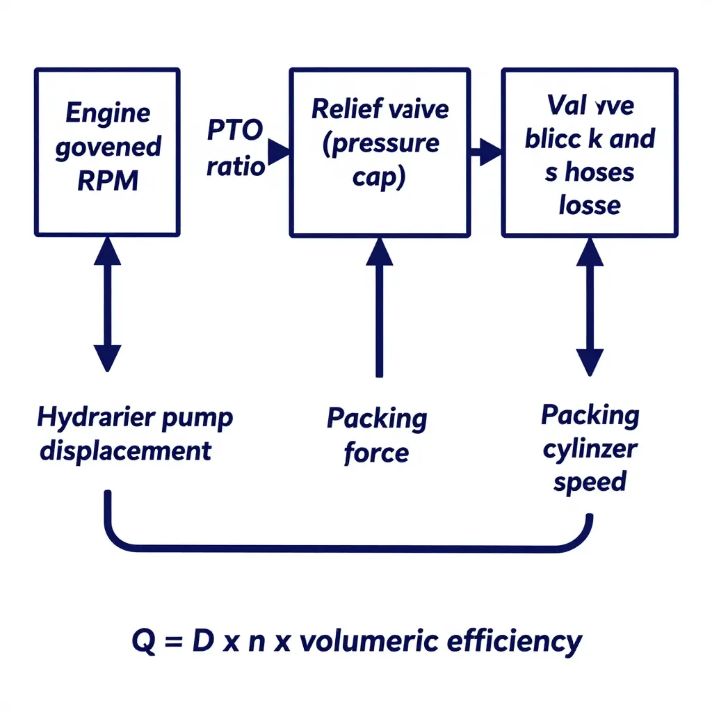
The Four Control Points a Buyer Can Specify
| Control point | What it sets | What it does not set |
|---|---|---|
| Pump displacement (cc/rev) | Flow at a given rpm, and therefore blade speed | Force or cycle time on its own |
| Pump drive rpm (PTO ratio x governed engine rpm) | The second flow multiplier | Flow if the pump is small |
| Relief valve setting (bar) | Maximum packer force and structural load path | Cylinder speed |
| Valve block and hose sizing | Pressure drop and heat at working flow | Force once the relief opens |
Pump drive rpm is where the PTO ratio becomes a specification rather than an afterthought. A 1.2:1 PTO behind an engine governed at 1,600 rpm gives 1,920 pump rpm. Choose a 0.9:1 ratio and the same pump delivers 25 percent less flow at the same engine speed. Slow packers on batch units usually trace back to this line.
The relief setting is often over-read. It caps achievable packing force, the pressure ceiling on the blade, but once the relief is closed it has no influence on how fast oil crosses the cylinder. Raising it to speed up the blade only adds stress and heat.
Circuit losses are the quiet tax. Undersized hoses, restrictive spool passages and a clogged return filter all shave flow before it reaches the cylinder, and pushing 120 L/min through a badly sized manifold can cost three to five percent of pump flow across the valve block, which is enough to crack the relief early and send that oil back to tank instead of to the blade.
Why a 5 Percent Flow Shortfall Matters
A shortfall in delivered flow lengthens the packing cycle almost in proportion, because the cylinder volume to be filled does not change. A 22-second stroke becomes about 23.2 seconds at five percent low, 24.4 seconds at ten percent, and 27.5 seconds at twenty percent.
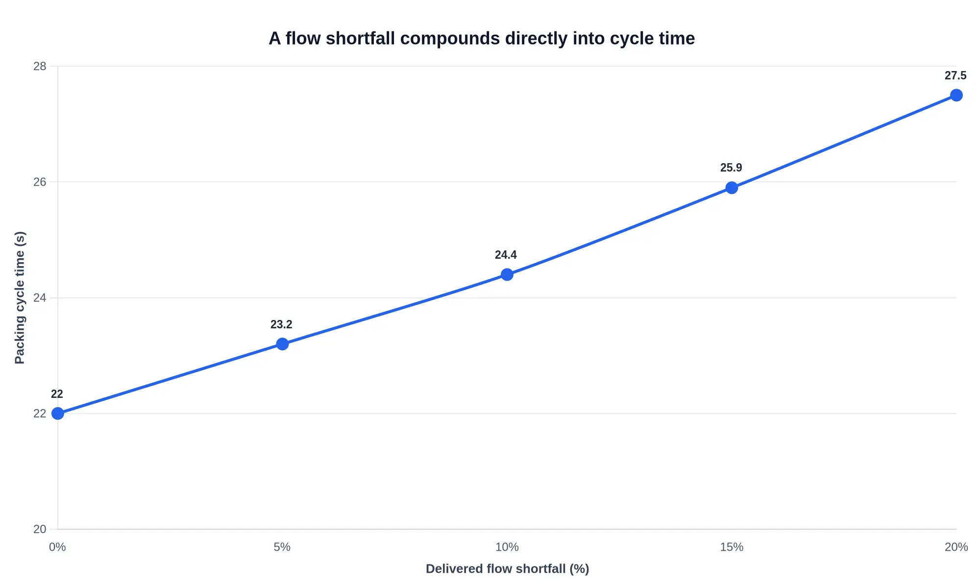
One second per stroke sounds trivial until the route arithmetic runs. At one pack cycle per stop across 900 stops, five percent adds roughly 17 minutes of packing time to the day, before traffic, before lunch, before the last transfer station window. A fleet that keeps the route and loses the time pays for it in overtime. On heavy wet loads the same shortfall shows up as a real difference in real-world compaction ratio and usable body volume.
The “Bigger Pump Is Faster” Assumption
A larger hydraulic pump shortens the compaction cycle time only if the rest of the circuit can carry the flow and the driveline can absorb the torque.
Upsizing displacement raises torque demand roughly in proportion: a 25 percent larger pump at the same pressure needs about 25 percent more torque from the PTO, the PTO shaft and the transmission take-off. An unmatched PTO shows up as shaft wind-up, spline wear and, on some chassis, a torque-limiting fault on the engine. A reservoir and cooler that were not resized turn the extra flow into heat. Oil temperature climbs, viscosity falls, volumetric efficiency drops, and the pump you paid to upsize delivers less usable flow than the smaller unit did cold.
The sequence that works: size the pump to the flow the cylinder genuinely needs, then confirm PTO torque capacity, reservoir volume and cooler duty at that flow. An oversized pump that is not matched to the driveline buys heat and wear, not speed.
Delivered flow, not nameplate pump size, is what sets packing cycle time. Specify pump displacement, PTO ratio and governed engine rpm as one agreed package before the build is released.
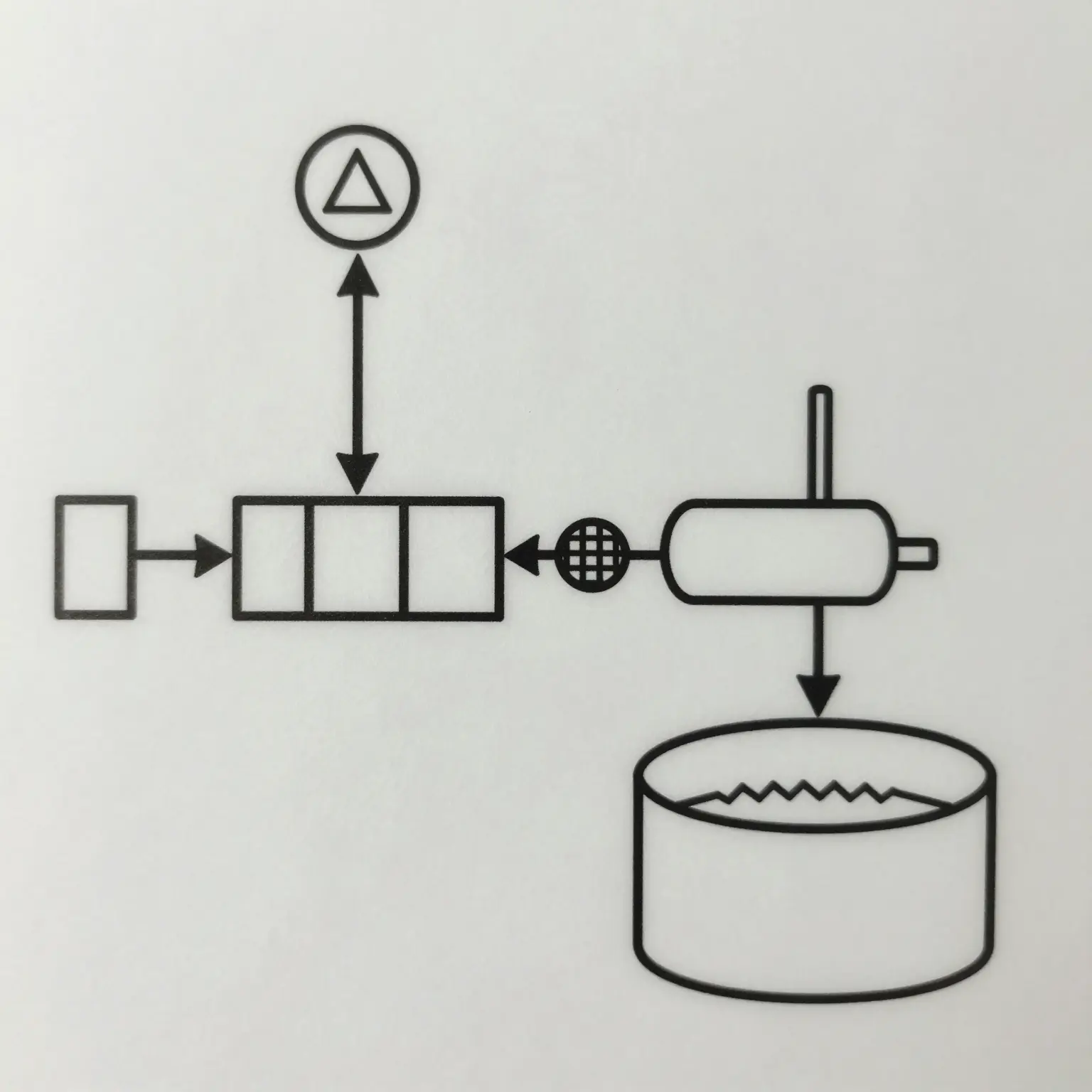
Figure: Packing hydraulic circuit, simplified. The PTO output shaft (bottom left) drives the pump, the pump sends volume to the control valve block, the valve routes it to the packing cylinder, and displaced oil returns through the filter and cooler to the reservoir. Follow the supply line: it carries litres per minute, not pressure, and the stroke time is set by how many of those litres reach the cylinder.
Batch Variance: Why Units From the Same Batch Pack at Different Speeds
Two trucks built a week apart, on the same drawing, in the same production batch, and one clears a hopper eight seconds sooner than the other. The spread rarely comes from the body or the blade geometry. It comes from hydraulic hardware tolerances that nobody wrote into the purchase spec. The causes below are the ones worth auditing on your next order.
- Pump displacement tolerance, unit to unit and brand to brand – Two pumps with the same nominal displacement can flow 3-5% apart at rated pressure, which moves a 22-second stroke by up to a second.
- PTO ratio selection differences – A ratio two steps off the specified value changes pump input rpm at the gearbox by roughly 10%, adding two to three seconds to each packing stroke.
- Governed engine speed at the PTO operating point – A governor trimmed 50 rpm below the specified PTO point cuts flow about 3% at a 1,500 rpm drive point, and every extend and retract pays for it.
- Relief valve setting drift affecting stall behaviour – A valve cracking 10-15 bar under setting bleeds flow through the heavy part of the stroke, turning a brief stall into a multi-second hesitation.
- Hose and fitting bore restrictions – Undersized fittings or long elbow runs throttle return flow, so blade retract slows and every cycle carries extra seconds.
- Oil viscosity and temperature at start of shift – Oil at 10 °C rather than 50 °C raises internal losses, so first-hour cycles run longer. This is the mechanism behind cold-start hydraulic stalls.
- Cylinder seal leakage and internal bypass – Bypassing rod or piston seals bleed flow past the piston, lengthening extend and retract times even when gauge pressure reads normal.
- Valve block spool type – Open-centre versus closed-centre spools, and meter-in versus meter-out control, deliver different usable flow, so identical pumps produce different stroke speeds.
These causes add rather than cancel, which is why the problem hides during a single-unit acceptance test. A pump at the low end of tolerance, a PTO ratio one step off and a relief valve set a little soft can stack into a spread across the batch that the buyer never agreed to.
Six trucks from one batch, built to one order sheet, should behave like six copies of the same machine. These six did not. All share a nameplate specification: a pump rated at 60 L/min, a nominal packing cycle of 24 seconds, and the same PTO ratio written into the sales file. Tested back to back at the specified PTO operating speed, with oil at working temperature and the relief valve verified, they produced a 9.4-second spread in packing cycle time.
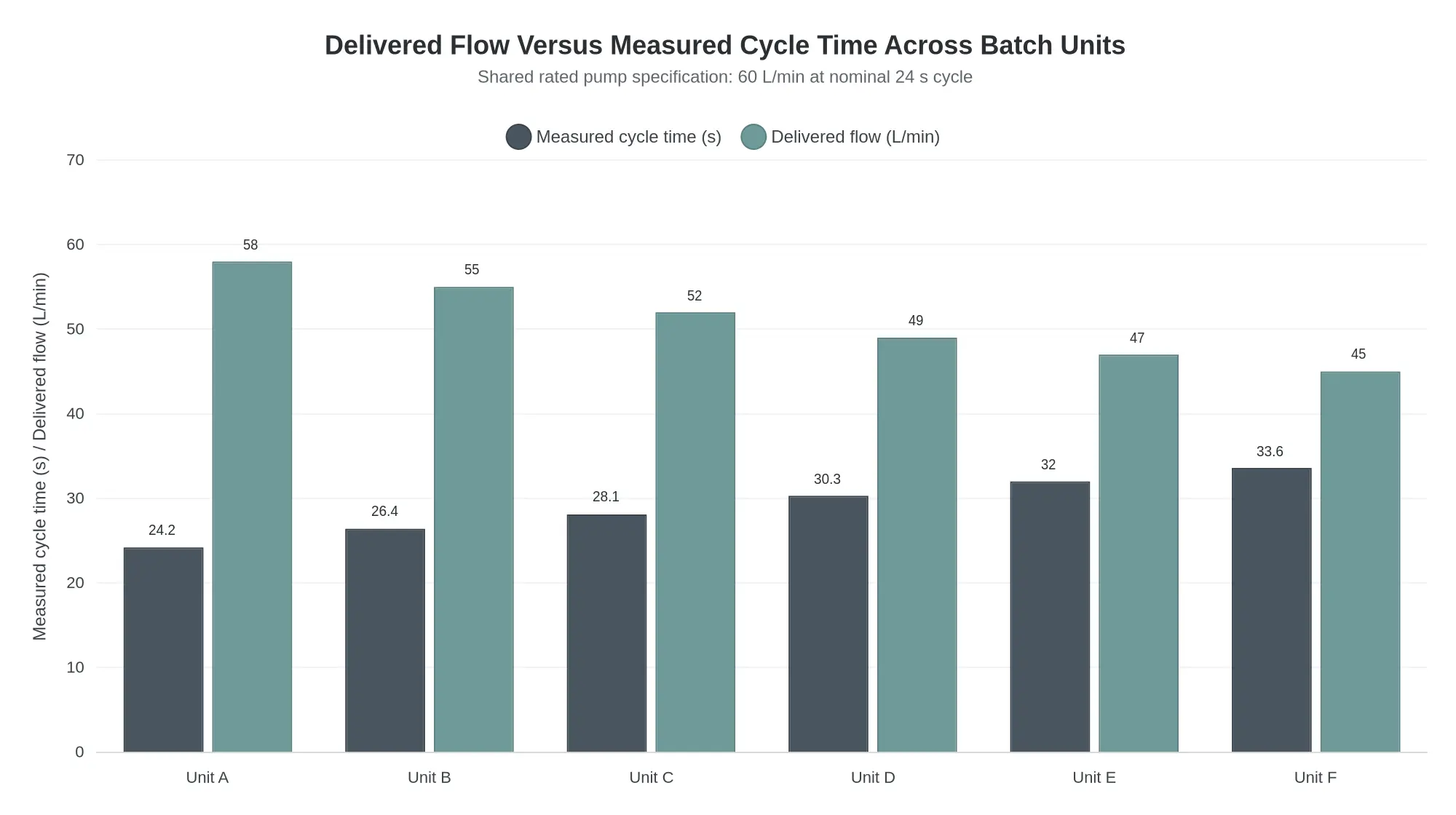
The dark grey bar is measured packing cycle time in seconds, on the left axis. The teal bar is delivered flow at the recorded PTO speed, on the right. The two series move in opposite directions: every litre per minute that fails to reach the packer cylinder becomes seconds on the stroke. Unit A delivers 58 L/min and completes the cycle in 24.2 seconds. Unit F delivers 45 L/min and needs 33.6 seconds for the same stroke, same blade travel, same body.
The money is not in a single cycle. On a 900-stop collection route running one pack cycle per stop, a 9.4-second penalty per cycle adds roughly 2.3 hours of shift time, absorbed by overtime or by a dropped portion of the route. In a two-shift municipal operation the same drift shows up as a truck that returns late every day while its twin returns on schedule, with identical payload ratings on paper.
The spread almost never comes from the pump model number. It comes from the conditions the rating was measured under and the installation the pump went into: effective PTO ratio and actual pump drive speed, suction line diameter and bend count, valve block pressure drop, relief valve setting, oil temperature at the start of the shift, and whether the pump was matched to the cylinder bore and rod ratio rather than to the truck’s gross weight. A flow figure quoted without a stated speed, oil viscosity and pressure is a marketing number. Buyers who want to see how cycle time converts into route capacity can check how compaction ratio changes what a rear loader actually packs before fixing body volume against a nominal cycle figure.
That is why the specification section that follows is written as a set of locked values rather than a list of preferred brands. Flow at the PTO, not flow on the pump label, is what the packer feels.
Hydraulic Pump Specification: What to Lock on the Purchase Order
“Heavy-duty hydraulic pump” and “matched to packer” are how batch trucks end up packing at different speeds on the same route. The pump is the flow source that sets blade stroke speed, so every value below belongs in writing on the PO and on the build sheet, with tolerances as percentages rather than a single nominal figure.
1. Pump Type and Displacement (cc/rev, With a Percentage Band)
Name the architecture first: fixed displacement external gear pump, or variable displacement load-sensing piston pump. Then state displacement with a tolerance band, for example “45 cc/rev, +/- 2% at 1,200 rpm, 200 bar, 50 C oil.” A bare “45 cc/rev nominal” lets the supplier’s band do the work: if that band is +/- 3%, a unit at the bottom delivers about 6 percent less flow than one at the top, enough to change pack cycle time on a wet load.
2. Rated and Peak Pressure, With the Relief Setting on the Build Sheet
Record both numbers and the duration attached to each: rated continuous pressure (for example 210 bar) and peak or intermittent pressure (for example 250 bar for no more than 10% of the cycle). The relief valve setting – say 225 bar at declared flow – belongs on the build sheet with the serial number, verified with a gauge at pre-delivery inspection rather than inherited from a catalogue page.
3. Drive Speed Limit and Flow at the Declared PTO Speed
Two figures are needed: the pump’s maximum continuous drive speed (for example 3,000 rpm) and the PTO operating speed the body was designed around (for example 1,200 rpm). Convert that to litres per minute: 45 cc/rev x 1,200 rpm = 54 L/min theoretical, which at 90% volumetric efficiency is about 48.6 L/min at the packer valve.
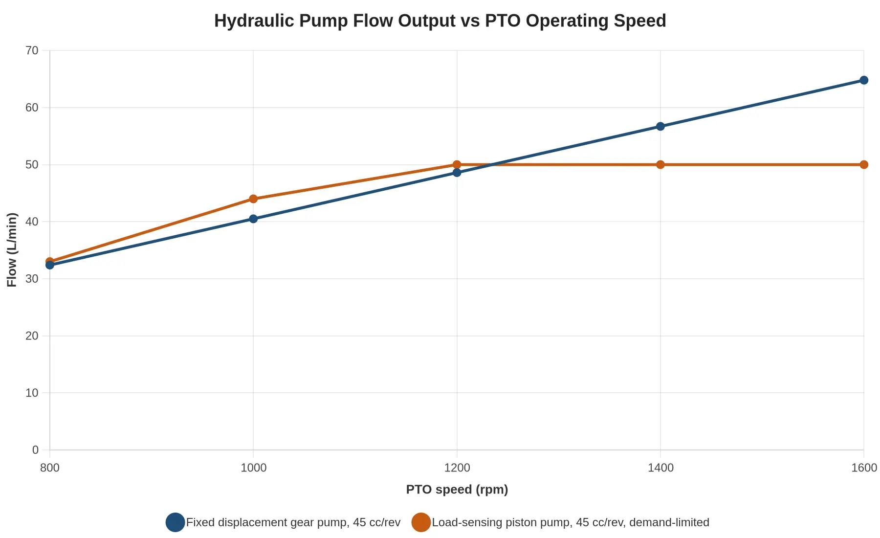
A gear pump’s output tracks drive speed, so a truck idling lower in the yard packs slower than the same specification running at full PTO rpm. That is one reason two batch units behave differently.
4. Mounting and Shaft Interface Standard
Fix the interface so pumps are interchangeable across the batch: SAE B two-bolt flange with a 13-tooth SAE spline, or ISO 7653 where the gearbox is European. Also specify pilot diameter, bolt circle, shaft end, direction of rotation, and port type and thread (SAE ORB or BSPP). Interface drift is a quiet source of misalignment, seal weep and coupling wear.
5. Control Type and Cycle Consistency
A fixed displacement gear pump is simple and cheap, but it delivers flow as a function of speed, so cycle repeatability depends on the driver holding rpm. A load-sensing piston pump with pressure compensation holds the commanded flow regardless of engine speed within its operating band and gives consistent blade stroke timing across a fleet – provided the directional valve is also load-sensing. The pump alone will not do it.
6. Volumetric Efficiency at Operating Temperature
State a tested figure, not a claim: 90% or better at rated pressure and 60 C oil, measured at factory acceptance with the result attached to the build record. Efficiency quoted at ambient temperature flatters a worn or loosely clearanced pump.
7. Fluid Cleanliness Class and Filter Micron Rating
Specify an ISO 4406 class – 18/16/13 for gear pumps, 17/15/12 for piston – plus a 10 micron absolute return filter rated beta 200 or better, with a bypass indicator and a documented flush before commissioning.
The Hidden Variables: Wear and Cold Oil
Used and rebuilt pumps rarely fail outright; they simply deliver less. If you are buying second-hand rather than new-build, read what PTO hours and hydraulic pump wear tell you before you bid, because a worn unit can sit inside its displacement tolerance while losing 8-10% of flow.
Temperature matters as much. Thick cold oil starves the pump inlet on the first lifts of the shift, which is why cold morning lifts stall before the oil warms. Specify an oil viscosity range of roughly 16-40 cSt at operating temperature, and note the maximum cold-start viscosity the pump will tolerate.
Manufacturer and Part Number, Not a Description
The PO should carry the pump manufacturer, the exact part number, the control suffix and the relief setting, never a generic description. Any substitution, including a “comparable” unit from the same maker, should require written approval issued as a deviation before build. If it is not approved in writing, it is not the specified pump.
| PO Field | What to Write | Example Entry |
|---|---|---|
| Pump type | Architecture and control | Load-sensing variable piston |
| Displacement | cc/rev with percentage band | 45 cc/rev +/- 2% |
| Rated pressure | Continuous bar | 210 bar |
| Peak pressure | Bar and duration | 250 bar, max 10% of cycle |
| Relief setting | Bar at declared flow, on build sheet | 225 bar at 48 L/min |
| Drive speed | Max continuous rpm | 3,000 rpm |
| PTO speed and flow | rpm and L/min at that rpm | 1,200 rpm, 48.6 L/min |
| Mounting and shaft | Standard and spline | SAE B 2-bolt, 13T spline |
| Volumetric efficiency | % at temperature and pressure | 90% at 60 C, 200 bar |
| Cleanliness and filtration | ISO 4406 class, micron rating | 17/15/12, 10 micron absolute |
| Identification | Manufacturer and part number | Maker name plus full part number |
Eleven lines on the PO, and batch consistency stops depending on luck.
Use the matrix to fix the hydraulic package before the build sheet is frozen. Flow is displacement multiplied by pump speed at the stated PTO ratio, and every row agrees at a governed engine speed of 1,500 rpm. Cycle times assume single-stage packing cylinders with a standard bore on the small bodies and stepped bores as volume rises, and tie back to how compaction ratio sets body volume.
| Body volume (m3) | Pump displacement (cc/rev) | Target flow (L/min) | Relief pressure (bar) | PTO ratio and drive type | PTO torque rating (Nm) | Target packing cycle (s) |
|---|---|---|---|---|---|---|
| 6 | 50 | 75 | 180 | 1.00, direct engine PTO | 220 | 22 |
| 8 | 60 | 90 | 190 | 1.00, direct engine PTO | 280 | 24 |
| 10 | 63 | 104 | 200 | 1.10, clutchable side PTO | 300 | 27 |
| 12 | 75 | 124 | 200 | 1.10, clutchable side PTO | 350 | 30 |
| 16 | 90 | 159 | 210 | 1.18, hot-shift side PTO | 430 | 34 |
| 20 | 100 | 186 | 210 | 1.24, hot-shift side PTO | 480 | 39 |
- Engineering starting points only – confirm displacement, relief setting and PTO torque against the specific body, cylinder bore and OEM rating before release to build.
PTO Specification to Lock Before Build
The power take-off (PTO) parameters below have to be agreed, documented and frozen before the batch build is released. Every value is a build-sheet item or an acceptance-test item, not a verbal assumption. Two identical rear loader bodies on the same chassis model will pack at different speeds if any one line here drifts.
PTO Type and Mounting Position
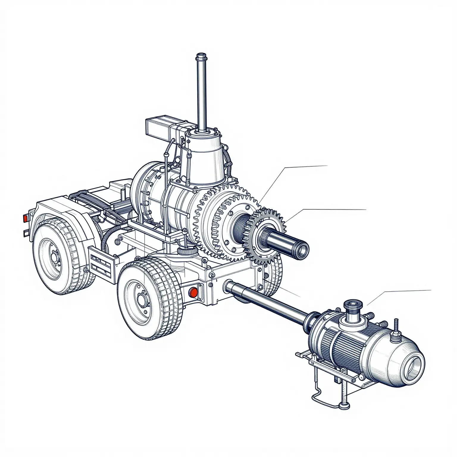
Specify a side-mount, gear-driven PTO on the transmission PTO aperture, independent of the engine flywheel, with the pump flange facing rearward and clear of the frame rail and exhaust routing. State the gear mesh arrangement explicitly: transmission PTO drive gear tooth count, PTO input gear tooth count, helix angle, backlash tolerance and the lubrication path at the mesh.
- PTO drive gear: 38T | PTO input gear: 30T | mesh ratio 1.27:1 overdrive
- Mounting position: left-hand transmission aperture, output shaft parallel to frame rail
- Clearance check: minimum 25 mm to frame, 100 mm to exhaust and DPF heat shields
The mesh arrangement is the most common source of under-speed pumps on batch units: the ratio charted is not always the ratio delivered.
Ratio and Pump Drive Speed
State the ratio and the resulting speed at governed engine rpm, and require the calculation to be printed in the order confirmation, not just the ratio figure:
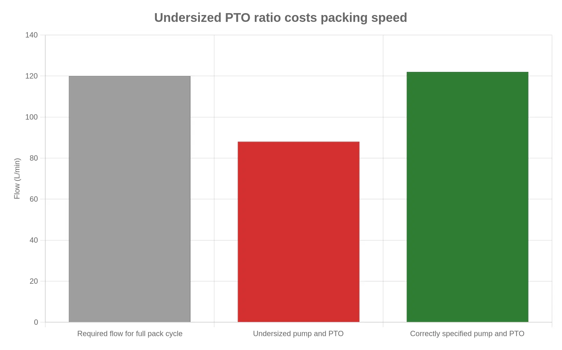
Pump speed = engine governed rpm x PTO ratio = 2,000 rpm x 1.27 = 2,540 rpm
Flow = displacement x speed = 48 cc/rev x 2,540 rpm / 1,000 = 121.9 L/min
With that line on the confirmation, delivered flow can be audited without a dyno run.
Torque Rating and Margin
Size the PTO against the pump’s absorbed torque, not the engine’s peak torque:
- Absorbed torque at 210 bar, 48 cc/rev, 0.92 mech. efficiency: approx. 174 Nm
- Required PTO continuous rating: 250 Nm minimum (approximately 43% margin)
- Required peak/intermittent rating: 300 Nm
Document the margin in writing. A PTO sized at 1:1 to absorbed torque survives the first month and fails in the second.
Output Shaft, Spline and Flange
The output interface must match the pump shaft as a complete, named standard, not a dimension sketch:
| Interface | Specification |
|---|---|
| Shaft | DIN 5462 / SAE 1-3/8 in 21-spline (state one) |
| Flange | SAE A 2-bolt, pump-mount pilot concentricity max 0.10 mm |
| Coupling | Direct-mount flange, no intermediate shaft |
| Fasteners | Grade 10.9, torqued and marked |
Engagement Method
Compare the three options on repeatable engagement timing, because delayed engagement is routinely read as a hydraulic fault:
| Method | Typical engage time | Repeatability | Notes |
|---|---|---|---|
| Mechanical (cable/lever) | 0.5-1.5 s | Low – operator dependent | Cheapest; timing drifts with cable stretch |
| Pneumatic | 0.3-0.6 s | Medium | Needs dry air and a dedicated valve; seal wear over duty cycles |
| Electronic (air or electric actuator) | 0.2-0.4 s | High – ±0.05 s | Best for batch consistency; requires CAN or relay logic and diagnostics |
For wholesale batch fleets, electronic engagement is the safer lock. Identical engagement timing across units removes the largest variable in perceived packing speed.
Interlocks and Safety Logic
Mandatory logic, verified on every unit:
- PTO engages only in neutral with park brake applied
- Engine speed inhibit above 800 rpm during engagement
- Engagement blocked with body raised or tailgate open
- PTO disengages on park brake release or neutral-switch loss
- Pressure relief set below PTO peak rating; thermal cut-out on oil temperature
- Cab indicator for PTO engaged and PTO fault
Lubrication and Cooling
State the lubrication source unambiguously: engine oil pressure feed to the PTO (preferred) or splash lubrication from the transmission (acceptable only at low duty). If splash-lubricated, cap the continuous duty accordingly.
Specify a hydraulic oil cooler where continuous flow exceeds 100 L/min and reservoir volume is below 60 L. At the 122 L/min specified here, a cooler is required. State its rated heat rejection rather than simply noting that one is fitted. Skip this and the slow cycle times that follow get misdiagnosed as packer blade faults rather than flow shortfall.
Duty Rating
Lock the duty class in writing:
- Continuous rating: 250 Nm at full 122 L/min, oil temperature stable at 70 °C or below
- Intermittent rating: 300 Nm for 2 minutes in 10 (pack cycle on/off pattern)
- Duty cycle assumption: 40% on-time over an 8-hour route shift
Where units are bought at auction or as used stock, PTO hours and hydraulic pump wear tell you most of what the hour meter will not.
Build Sheet vs Acceptance Test Record
Split the documentation so nothing is assumed:
| Parameter | Build Sheet | Acceptance Test Record |
|---|---|---|
| PTO make, model, type and mounting position | Yes | Verified visually |
| Gear mesh tooth counts and mesh ratio | Yes | Verified against stamping |
| PTO ratio and calculated pump speed at governed rpm | Yes | Measured speed check |
| Torque rating and stated margin | Yes | – |
| Spline and flange standard | Yes | Verified fit |
| Engagement method and target engage time | Yes | Timed engagement, 10 cycles |
| Interlock logic schedule | Yes | Function test, all interlocks |
| Lubrication source and cooler specification | Yes | Oil temperature at 30-min run |
| Duty rating (continuous/intermittent) | Yes | Flow and pressure at rated condition |
Sign both documents before the batch proceeds to body fitment. Anything not on the build sheet will not be on the truck.
The PTO Drive Interface, Stripped Down
Before arguing about packing speed on a quote sheet, agree on the hardware that makes the packer move. Every rear loading compactor body is fed by one chain: engine flywheel housing, power take-off gear, PTO output shaft, coupling, hydraulic pump. When two batch units built to the “same” spec pack at different speeds, the divergence almost always sits somewhere on that chain, not in the packer cylinder. A flywheel housing drilled for a different PTO aperture, a gear set with a different ratio, a shaft and coupling that are mismatched, or a pump substituted at the last minute will all change cycle time without changing a single number on the body drawing.

The diagram is deliberately schematic, not a service drawing, so nobody can hide behind a part number. Point at each block in the build meeting and get a written answer.
Four questions the schematic forces you to answer
- Flywheel housing and aperture. Which housing is on the chassis, and is the PTO aperture pattern confirmed against the engine model rather than the engine family name? Housing mismatch is the number one cause of a pump that “arrives late and fits badly” on a batch order.
- Gear ratio and direction of rotation. The PTO gear is driven by the flywheel drive gear, so ratio sets pump speed and rotation direction sets whether the pump is valved correctly at all. Lock both in writing before the order goes to the build line.
- Shaft, coupling and alignment. Shaft length, spline count, pilot diameter and coupling type must be specified as one assembly. A coupling chosen to “fit on site” is where energy loss and premature wear begin.
- Pump body interface. Mounting flange, port orientation and displacement must match the ratio above, or the body will pack slowly and the pump will run hot while every threshold reading still looks acceptable.
| Interface point | What to lock in the purchase spec | What goes wrong if it is left open |
|---|---|---|
| Flywheel housing / PTO aperture | Engine model, housing part number, aperture pattern | PTO will not seat; late rework on the build line |
| PTO gear ratio | Ratio and direction of rotation stated numerically | Different pump speeds across units in the same batch |
| Output shaft and coupling | Shaft length, spline count, coupling type as one item | Vibration, coupling wear, hydraulic fade under load |
| Pump flange and displacement | Flange standard, port orientation, displacement | Slow pack cycles, heat build-up, no clear warranty path |
One practical habit: ask for the PTO gear ratio and pump displacement to be printed on the build sheet next to the packer cycle specification, so the three cannot be approved separately. Buyers auditing second-hand or ex-fleet units can apply the same logic in reverse, using PTO hours and hydraulic pump wear as a pre-bid check to judge whether the drive interface was ever specified properly.
Build Acceptance and Verification Protocol
The sequence below turns the agreed hydraulic and body specifications into a witnessed record. Every step produces a number for the build sheet, never a verbal confirmation.
- Log the hardware before assembly. Record the pump part number, the PTO part number, and the pump-to-PTO drive ratio on the build sheet before the first hose is connected, so the delivered unit can be traced to the components quoted.
- Verify the drive speeds. Confirm the governed engine speed and measure actual pump drive speed with a tachometer at high idle, then record both figures against the specification.
- Measure delivered flow hot. At normal operating temperature, measure flow at the packing valve inlet with a flow meter and record it beside the declared figure for that model.
- Set and record relief pressure. Adjust the relief valve to the specified setting, confirm it with a gauge, and enter the reading on the record.
- Run a defined cycle count. Complete a stated number of packing cycles on a test bin load of known material and record elapsed cycle time per stroke.
- Sign off against the tolerance band. Have the inspector sign the completed record against the tolerance band stated in the purchase order, with any deviation noted rather than erased.
A cycle-time figure without a recorded flow measurement is not a verifiable acceptance criterion. It can be produced by a different governed speed, a different relief setting or a warmer test load, and nobody downstream can tell which. Require the flow and cycle-time record as a delivery document, countersigned against the PO tolerance band, so the unit stays traceable to the pump and PTO combination actually installed. Keep cycle time and compaction ratio in the same evaluation: a fast cycle on a low-ratio body just moves more air around.
Where Packing Cycle-Time Variance Actually Comes From
Once the acceptance protocol closes out, one question remains: if every truck in the batch was built to the same drawing, why does one finish a full pack cycle nearly two seconds slower than the next? Across a recent batch audit the spread was consistent enough to chase, so we logged cycle times per pack, per unit, under matched load conditions, then separated the variance by cause. The result is less dramatic than most buyers expect, and it is the most useful data in this specification discussion.
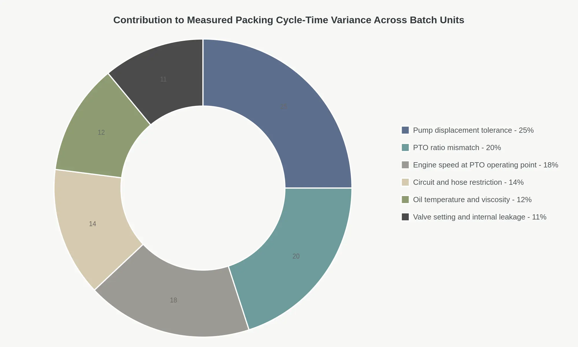
Three factors account for 63 percent of the measured spread, and all three are specification and setting problems: pump displacement tolerance at 25 percent, PTO ratio mismatch at 20 percent, and engine speed at the PTO operating point at 18 percent. None of them is a failure. Every one of those trucks would pass a pressure test and a functional inspection. They simply produce different flow rates, and flow rate is cycle time.
The remaining factors are just as controllable, even where they look more like operating conditions than build decisions. Circuit and hose restriction at 14 percent is a routing and sizing issue: a long run of undersized hose or one tight elbow costs flow on every cycle. Oil temperature and viscosity at 12 percent shifts with duty cycle and ambient conditions, but it can be pinned down by specifying the oil grade and the cooling capacity instead of leaving both to chance. Valve setting and internal leakage at 11 percent is the only slice where genuine wear hides, which is why packer blade and cylinder condition belongs in the conversation but not at the top of it.
What to Write Into the Build Specification
None of this needs a bigger pump or an upgraded valve block. It needs tolerances written into the purchase order and verified before the truck leaves the line. The table converts the chart into specification language.
| Variance source | What to lock in the build specification | Practical target |
|---|---|---|
| Pump displacement tolerance | Rated displacement and permissible deviation, verified on a bench report supplied with the unit | Plus or minus 1.5 percent of rated displacement |
| PTO ratio mismatch | PTO gear ratio matched to the pump, not to the gearbox default | Within 1 percent of the ratio stated on the pump curve |
| Engine speed at PTO operating point | Governed PTO speed stated as a number, checked at the flywheel with the PTO engaged | 1,650 rpm, plus or minus 25 rpm |
| Circuit and hose restriction | Hose bore, total run length and fitting count capped in the drawing | No more than 2 bar pressure drop at full flow |
| Oil temperature and viscosity | Oil grade, tank volume and cooler capacity specified for the duty cycle | ISO VG 46, 50 to 60 degrees C at steady state |
| Valve setting and internal leakage | Relief setting and leakage acceptance test recorded at pre-delivery | Relief within 2 percent of set pressure |
Read the chart the other way and the argument gets sharper. A buyer who swaps in a premium pump without touching PTO ratio, engine speed governing or hose sizing pays for the pump and addresses a fraction of the problem. Specification control is cheap, it is auditable, and it acts on nearly two thirds of the spread. Lock the numbers before the build, inspect them at acceptance, and the batch packs at one speed instead of six.
FAQ: Pump, PTO and Packing Cycle Questions Before Build
Does a higher-flow pump always reduce packing cycle time?
No, not on its own. Cycle time is cylinder volume divided by effective flow, and effective flow is what gets past the relief valve. If the circuit already lifts the relief during the heavy part of the stroke, extra pump capacity leaves through the relief as heat. Where it does not, a larger pump does shorten the stroke: 12 L of cylinder volume takes about 12 s at 60 L/min and about 8 s at 90 L/min, provided PTO torque rating, hose bore and cooler capacity follow.
Which PTO ratio should a buyer specify for a given pump displacement?
Specify the PTO ratio so pump rated speed is reached at working engine RPM. A pump rated 1,800 rpm driven at 1,400 rpm needs a 1.29:1 step-up; a 1:1 direct mount under-speeds it and cuts delivered flow roughly 22%. State engine RPM, PTO ratio and pump displacement in cc/rev on the hydraulic pump and PTO specification.
Can a pump change alone fix slow packing on an existing unit?
Rarely. Slow packing usually traces to worn packer blade contacts, a clogged return filter, or a relief set at 175 bar where the build sheet calls for 210 bar. Fitting a larger pump without matching PTO torque rating, 25 mm hose and cooler capacity only relocates the bottleneck. Run packer blade wear checks before changing hydraulic hardware.
What tolerance band should the purchase order state for cycle time and delivered flow?
Write ±10% on cycle time at rated engine RPM (for example 18 s ±1.8 s for a full pack stroke) and ±5% on delivered flow measured at the pump outlet at 200 bar and 50 °C. Fix the test oil at ISO VG 46 and state the measurement point, otherwise the band is unenforceable.
How much does oil temperature affect measured packing speed at the start of a shift?
Significantly. ISO VG 46 at 10 °C is roughly ten times more viscous than at 50 °C, so pressure drop across filters and valve galleries rises and a 17 s pack cycle can stretch to 24 s. Measure packing speed at 45-55 °C, or specify a thermostatic bypass and a proper warm-up procedure.
Should a load-sensing pump be specified instead of a fixed displacement gear pump?
Only where the body runs proportional valves or several functions at once. A single-circuit rear loader with one pack circuit is better served by a fixed gear pump at 60-70 L/min with an unloading valve: simpler, cooler and cheaper to service. Load sensing pays back mainly on multi-function automated bodies.
What to Lock Before Build
Packing speed is not driver technique, and it is not a break-in period that eventually settles things down. It is a flow-governed outcome, set by the hydraulic circuit as specified, and once the specification is signed it stays fixed for the life of the unit. Two trucks built to the same body drawing will still cycle at different rates if the pump and PTO behind that body differ, which is why a bare cycle figure in a quotation is worth very little at acceptance.
Four values have to be locked in writing before the build is released:
- Pump displacement, with its tolerance band, so delivered volume per revolution is a number rather than a nominal one.
- Relief pressure, so the circuit’s working ceiling is defined and repeatable across the batch.
- PTO ratio, together with the resulting pump drive speed at rated engine rpm. The ratio alone says nothing without the engine side of the equation.
- Delivered flow at operating temperature, because cold-oil flow figures overstate what the packer receives once the circuit is warm.
Those four values, read against a measured cycle-time record taken from a running unit, turn an ambiguous performance claim into an enforceable acceptance criterion. A quoted “packs in X seconds” cannot be rejected or defended at handover; a displacement, a relief setting, a PTO ratio, a warm-oil flow figure and a timed record can.
As a special vehicle manufacturer operating under CRRC’s quality system, we record pump and PTO part numbers, ratio and flow test results on the build sheet for every unit. Packing performance and payload limits are set together at specification stage, so the payload versus axle weight trade-off belongs in the same conversation as the pump and PTO figures, not in a separate one after the chassis is chosen.