Opening Diagnostic Overview
A tipper body that rises unevenly, with the rear gate and side rails drifting out of level during the raise, is a geometry fault before it is a hydraulic one. Crooked lift on a tipper garbage truck comes down to two causes that feed each other: a crowned road cross-slope loading the chassis asymmetrically as the body comes up, and hinge pin wear that lets the rear pivot drop on one side.
A crowned road puts the high side of the pavement under one wheel path and the low side under the other, so the frame rails take an unequal load before the hoist strokes. The body then follows the frame, and the gate finishes the raise sitting off level against the ground line rather than against the chassis datum. Crews who judge the lift by eye on a crowned road will either log a fault that does not exist or miss one that does.
Hinge pin wear accumulates as a slow oval in the bushing, and the resulting clearance converts a square pivot into a rocking one. Once radial clearance passes a few tenths of a millimetre, the rear of the body shifts laterally under load and the side rails show a lean that grows with every raise. The hinge pin and bushing clearance figures worth recording belong in the unit file, not in a mechanic’s memory.
A crowned road and a worn pivot rarely appear alone, because crown accelerates bushing load on the low side and each fault makes the other worse over a shift. The checks that separate them are plumb and level readings at the gate, pin and bushing diameter logs, frame rail and subframe inspection, and the hydraulic balance points that can mask a mechanical fault. What decides whether the unit stays in service is a measurement, not an opinion about how the lift looked.
Reading the Diagnosis at a Glance
Crooked lifting on a crowned road is rarely a hydraulic fault on its own. It is a geometry problem that starts where the tyres meet the surface and ends where the body leaves the subframe.
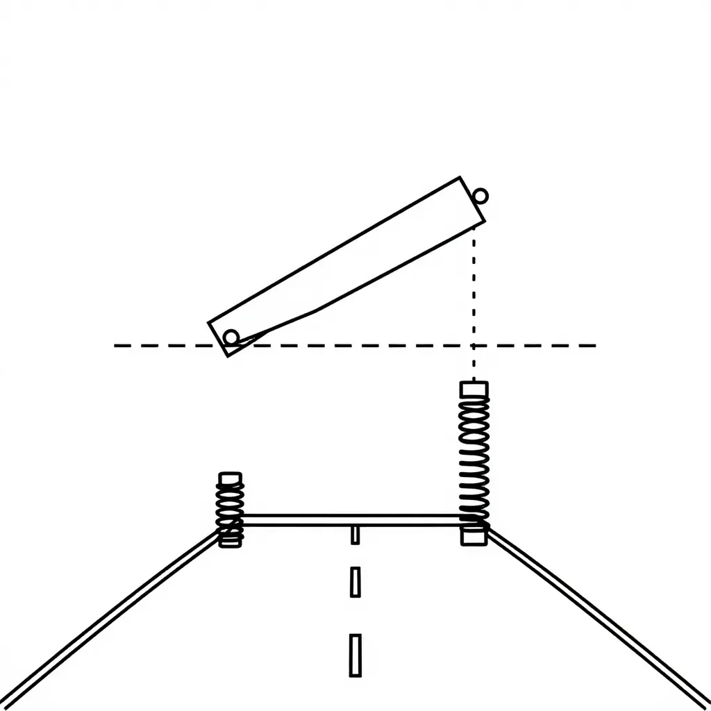
Schematic of frame roll on a crowned road: the crowned road tilts the chassis, the unequal spring compression translates that lean into frame roll, and the raised hinge geometry converts it into visible body tilt.
Watch the dashed reference line. Every degree the body axis sits off true horizontal has to be absorbed somewhere, normally at the rear hinge pin and its bushings. After a few seasons of crooked lift, that wear shows up as ovality rather than as a clean, round bore, which is why hinge pin wear measurement belongs in the same inspection as the crown and the springs.
Crowned-Road Geometry and the Torsional Load Path
A crowned carriageway is built with a deliberate cross-slope – normally between 1.5 and 3 percent from the centre line down to the shoulder – so that surface water drains. For a light vehicle that slope is invisible. For a tipper garbage truck with a loaded body sitting well above the frame rails, it is a continuous, measurable torsional input into the chassis, and missing it means diagnosing a hinge or hydraulic fault where the geometry already explains the lean.
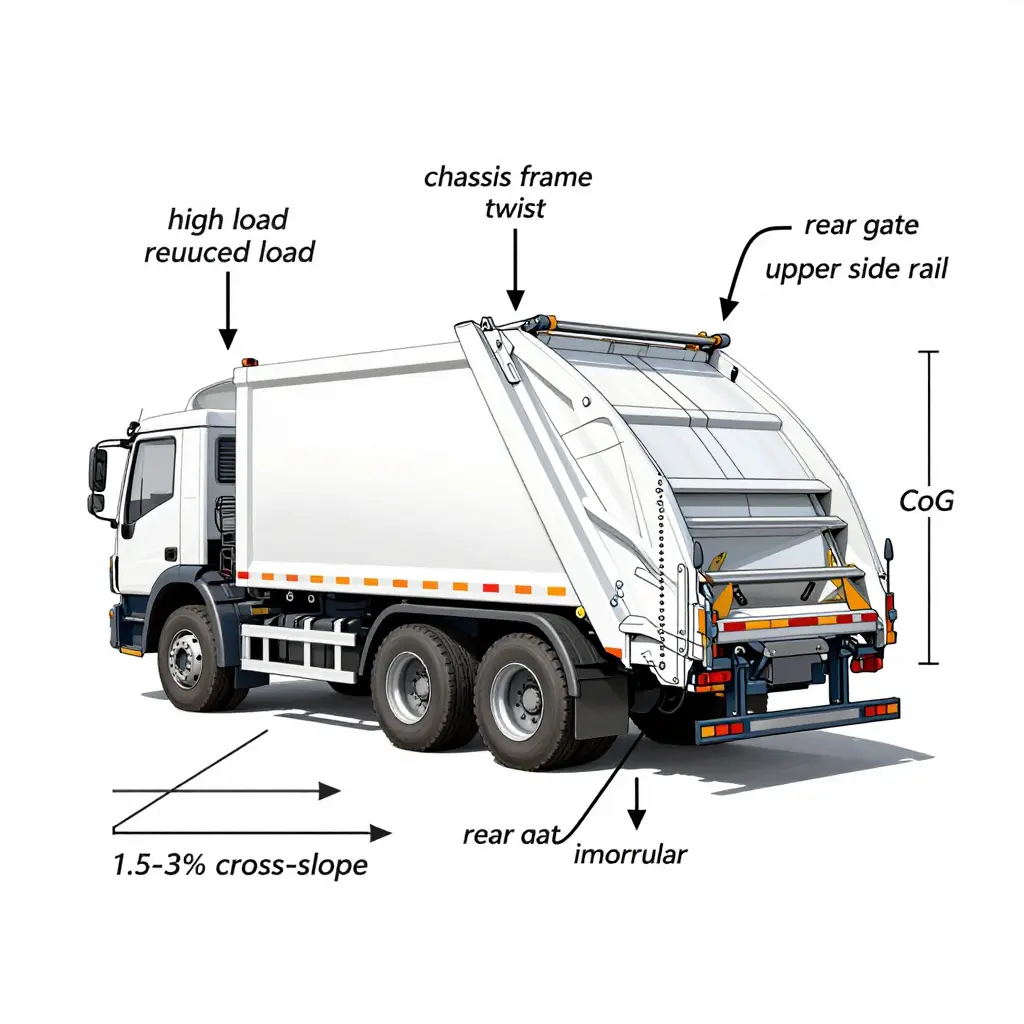
Unequal wheel loading and the offset centre of gravity
Driving on a cross-slope transfers weight diagonally. The downhill wheels carry more vertical load and the uphill wheels carry less, so the left and right suspension springs are compressed by different amounts. The loaded body’s centre of gravity sits high – typically 1.6 to 2.0 m above the road on a refuse body – and that height multiplies the effect: the loaded CoG shifts laterally toward the downhill side by roughly the CoG height times the cross-slope tangent.
| Cross-slope (%) | Road angle (deg) | Lateral CoG shift per 1 m of CoG height (mm) | Shift at 1.8 m CoG height (mm) |
|---|---|---|---|
| 1.5 | 0.86 | 15 | 27 |
| 2.0 | 1.15 | 20 | 36 |
| 2.5 | 1.43 | 25 | 45 |
| 3.0 | 1.72 | 30 | 54 |
That lateral shift loads one frame rail more than the other. The result is frame roll plus chassis frame twist – a torsional wind-up in which one rail is driven down at one corner while the diagonal corner rises, so the two rails respond out of phase.
How spring rate and subframe pads absorb or transmit the twist
Suspension spring rate sets how much of the road input becomes rail deflection. Softer springs and rubber subframe mounting pads between body and chassis act as a series compliance: they absorb a portion of the twist elastically and keep it out of the body structure. Harder spring packs, worn or collapsed rubber pads, and over-torqued or seized mounting bolts all short-circuit that compliance, transmitting the twist directly into the subframe and body. A truck that has recently had pads replaced with harder or incorrectly shimmed parts will often show a more pronounced crooked lift on the same road. Frame rail condition matters equally – hidden cracks concentrate stress at the point of maximum torsion, which is why inspecting frame rails for hidden cracks belongs in any pre-purchase or periodic inspection.
The hinge axis as a twist-to-tilt converter
The longitudinal hinge axis is what turns rail twist into a visible lean. The chassis rails twist about the vehicle’s longitudinal centre line, but the hinge pins hold the body to a single axis at the rear. Any rail twist that reaches the hinge brackets is resolved as rotation about that pin axis, so the body is displaced laterally – it leans toward the downhill side while the rails themselves appear almost level to the eye. This is the mechanism behind a tipper garbage truck body lift that looks crooked before the cylinder has even begun to extend.
Why the rear gate and upper side rails show it first
Torsional deflection accumulates with distance from the front axle and peaks at the extreme rear of the frame; it is also amplified in proportion to height above the hinge line. The rear gate, the top corners of the side rails and the upper tailgate frame therefore record the largest lateral movement. A driver notices the top rear corner drifting off-line long before any defect becomes visible at the subframe.
Two different tilts – keep the measurements separate
Do not confuse the two angles when diagnosing:
- Tilt relative to the chassis – measure the body’s angle against the frame rail top flange, using a digital inclinometer on both. A deviation here, with the truck on flat ground and the body fully down, points to hinge pin wear, an ovalised pin boss, a bent hinge bracket or uneven hydraulic cylinder output. It is a fault.
- Tilt relative to true horizontal – measure the body against a spirit level or inclinometer zeroed to gravity. A body that is square to the chassis but not level is following the road, not failing. It is a geometry and road-condition effect.
Zero both instruments on the same flat pad first. A body that reads level on the shop floor and leans on the shoulder has no fault. A body that leans against its own frame rail on that same flat pad does.
The causes below are ranked by how often they turn up in service, and each names the measurement that confirms it. For the full pin-and-bushing procedure, review the hinge pin wear inspection guide.
- Asymmetric hinge pin and bushing clearance: Measure pin diameter at four quadrants with a micrometer and compare bore clearance left to right. A side-to-side differential above 0.5 mm is the leading measurable indicator of tipper garbage truck hinge pin wear and the most frequent cause of a skewed lift arc.
- Unequal twin-cylinder extension or single-cylinder guide wear: Compare rod extension stroke on both sides through the full raise and log pressure at each cylinder port. A stroke differential above 3 mm is a fault flag on this check; a side-to-side pressure split above 10 bar indicates internal bypass or guide wear.
- Off-centre load distribution in the body: Check axle load readings per side on a level pad and confirm lateral centre-of-gravity position. An offset beyond the body builder’s tolerance, commonly 100 mm, loads one hinge line harder throughout the lift.
- Twisted or cracked subframe: Measure subframe diagonals cross-corner and check rail straightness against a taut line. A diagonal mismatch above 5 mm, or a crack at a crossmember weld, confirms torsional flex under load.
- Worn or collapsed suspension on one side: Record ride height at all four corners and compare spring pack or airbag deflection. A ride height drop above 10 mm on one side tilts the chassis and shifts body weight onto a single hinge.
- Worn body guide rollers and side pads: Measure roller diameter and pad-to-guide clearance with feeler gauges. Clearance beyond the specified 2-3 mm allows the body to yaw during the raise and edge-loads one side of the hinge.
- Restricted or mis-sequenced hydraulic flow: Log flow and pressure at each cylinder port and verify valve sequencing timing against spec. A flow deficit above 10 percent on one circuit, or a sequencing delay above one second, produces uneven extension.
- Bent or misaligned hinge lugs: Verify lug bore alignment with a mandrel or laser and measure lug-to-lug spacing. Misalignment above 1 mm per metre of span forces the pin into edge loading and accelerates scoring.
- Deformed frame rails: Measure rail height, flange square and web flatness against the OEM drawing. A web deflection above 3 mm across the hinge span reduces platform stiffness and amplifies every other clearance error.
Each symptom in the table is paired with the cause worth confirming, the measurement to record, and a limit; wherever the OEM value governs the verdict, it is named.
| Symptom observed | Probable cause | Measurement to take | Indicative pass/fail limit |
|---|---|---|---|
| Tilt only on crowned sections | Chassis cross-slope with uncompensated cylinder stroke | Cross-slope at each axle; rear-corner body-to-frame gaps on a level slab | Pass if body follows the crown within OEM cross-slope tolerance (often 1-2%); OEM spec governs |
| Tilt present on level ground | Unequal left/right cylinder stroke, bent rod, worn hinge bushings | Rod extension each side at mid-stroke, body empty, wheels on level slab | Fail if left-to-right stroke difference exceeds the OEM limit (typically 3-5 mm) |
| Tilt direction changes with load position | Frame or subframe twist; worn pin allowing lateral shift | Lateral pin play with a dial indicator while the load is repositioned | Fail if radial clearance exceeds 0.5 mm, or the lower OEM wear limit |
| Jerky or unequal cylinder extension | Air in circuit, damaged seals, restricted flow to one side | Per-side cycle time and full rod extension; rod scoring check | Fail if stroke difference or cycle time deviates more than 10% from OEM figures |
| Lateral sway at rear gate during the raise | Worn hinge pin and bushing clearance | Radial clearance at the pin boss with dial gauge or caliper | Pass at 0.3 mm or less; replace at the OEM limit (commonly 0.8-1.0 mm) |
| Knocking or fretting noise at the hinge point | Pin and bushing fretting, loose keeper, worn boss | Pin-to-bushing clearance plus keeper bolt torque | Fail if clearance exceeds 0.5 mm or torque falls below the OEM value |
| Grease extrusion or rust staining at the pin boss | Water ingress, blocked grease path, ovalized bore | Bore diameter at two axes 90 degrees apart; pin diameter | Fail if out-of-round exceeds 0.1 mm or clearance passes the OEM limit |
For the full replacement sequence and the wear thresholds behind these numbers, read hinge pin wear on rear-loader compactor bodies.
The Hinge Pin and Bushing Wear Mechanism
A tipping body hinge never wears out evenly, so the symptom shows up at the top of the raised body rather than at the pin. Two pins carry the rear weight of a full load through a set of lug eyes that only ever oscillate through a few degrees. There is no continuous rotation, no full oil film, and no self-cleaning action, so what you get is a slow, load-biased loss of material that starts in one narrow arc of the bore and works outward from there. Measure that arc early and the pin-wear inspection baseline for a rear-loader compactor hinge gives you a reference set of readings to compare against.
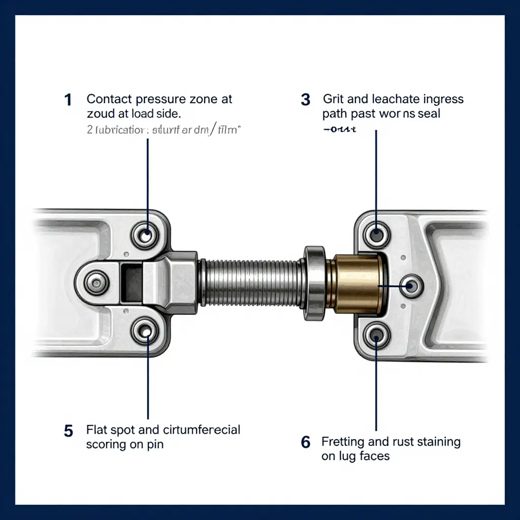
Contact pressure: the wear always starts on one side
Under load the pin does not sit centred in the bushing. The reaction from the body presses it against a narrow strip of bore, typically 60 to 120 degrees of arc on the side away from the lift cylinder. Unit pressure inside that strip is several times what a nominal bore-area calculation would suggest, and that is where the grease film collapses first. On the return stroke the load drops away but the pin does not reposition itself fully, so the same strip keeps taking the hit raise after raise.
Lubrication starvation
Grease reaches the bore through a drilling in the pin or the lug and a single nipple per hinge point. Anything that interrupts that path – a snapped nipple, a blocked drilling, a hardened plug of old grease, a seal lip that no longer holds pressure – leaves the loaded strip running dry through the first and hardest part of the raise. Starvation accelerates every other mechanism below, which is why a dry hinge can lose measurable bushing clearance in a single season while a greased one holds for years.
Abrasive ingress: road grit and refuse leachate
Worn end seals let two contaminants in at once. Road grit arrives as fine silica and acts as a lapping compound once it is worked into the clearance. Refuse leachate arrives as an acidic liquid carrying organic fines, and it attacks the seal lip and the lug faces while keeping the abrasive in suspension. The result is a slow grinding paste that removes material from both pin and bore and leaves a dull, grey-black surface rather than a polished one.
Ovalisation of the bushing bore
The bore stops being round before it stops being tight. Load-biased wear elongates it along the direction of load, so a bore that gauges 60.05 mm horizontally may read 60.60 mm vertically. Contact area falls as the oval grows, unit pressure rises, and the open channels at the ends of the ellipse give the grease somewhere to drain instead of where it needs to stay.
Flat-spotting and scoring on the pin
The pin develops a flat or a shallow dished area where it sits against the worn arc, and circumferential scoring where hardened grit has been dragged around the journal. Measure pin diameter with a micrometer at four positions 90 degrees apart at each end and at the centre; the spread between the largest and smallest reading is the roundness loss, and it belongs in the record next to the bore readings.
Fretting at the lug faces
Between the lug faces and the bracket, and under the pin shoulder, the movement is measured in hundredths of a millimetre but repeated thousands of times. That produces fretting: red-brown oxide powder, then a raised step and a widened axial gap. Check the step with a feeler gauge against a straight edge, and check axial float at the lug with a pry bar. A growing step there is often the first visible confirmation of hinge pin wear, well before the bore readings look alarming.
The lever ratio: 1 mm of bushing clearance becomes 17 mm at the top corner
The lever is what turns a pin measurement into a body symptom. A radial clearance at the pin lets the pin cock inside the bore, and the body converts that small angle into movement at the top corner over a long lever:
Lateral displacement at the top corner = clearance x (1 + lift height / bushing length)
Work the arithmetic on a rear-loader with 2400 mm from the hinge axis to the top corner and a 150 mm bushing: 1 + 2400 / 150 = 17. One millimetre of radial bushing clearance produces about 17 mm of lateral movement at the top corner. Use the bushing length, not the pin length, and measure lift height from the hinge axis, not from the subframe.
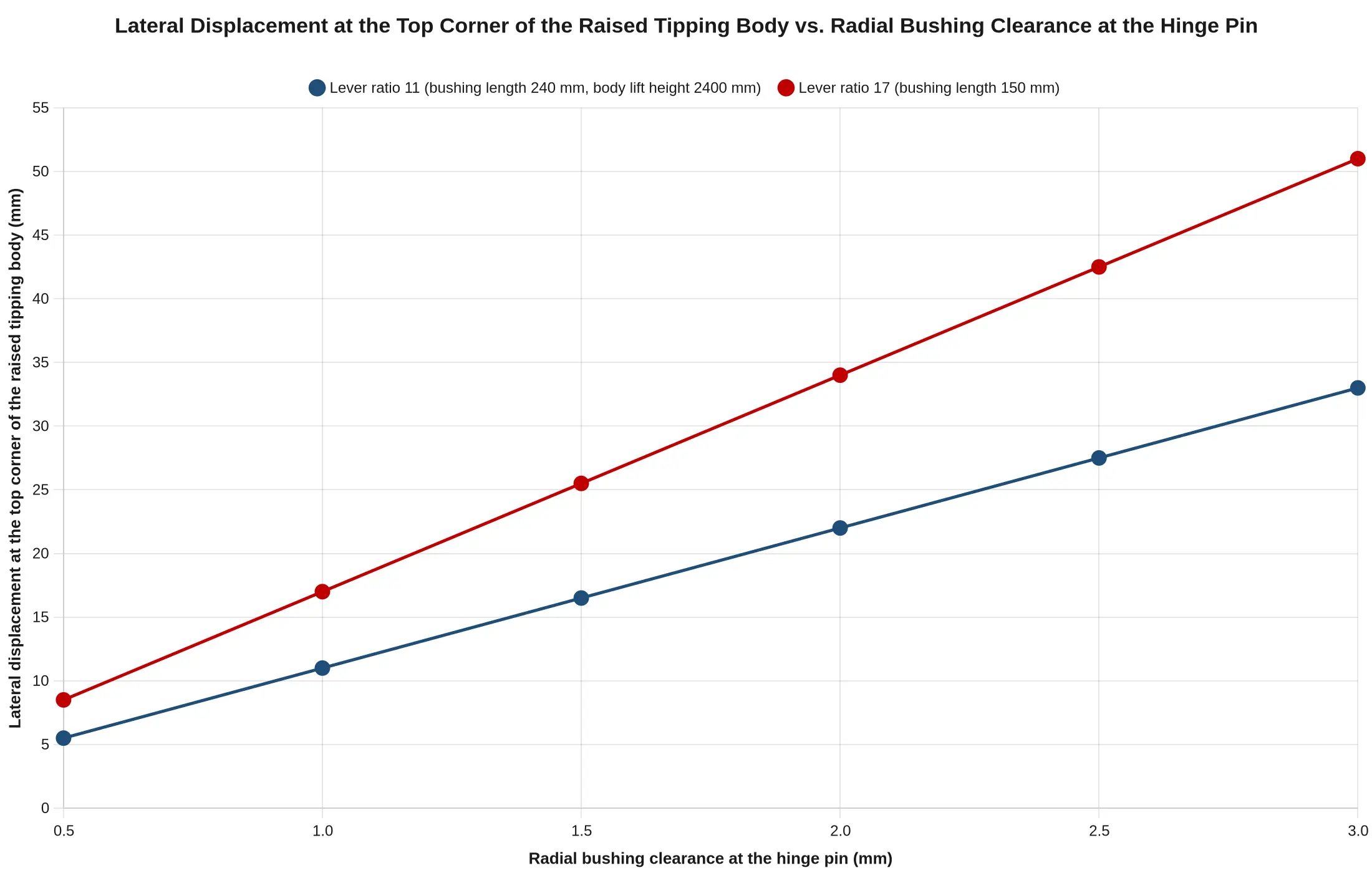
A short bushing on a tall body is the worst combination, and it explains why two trucks with nominally identical clearance readings lean by visibly different amounts. Record the geometry with the wear numbers so the calculation means something:
| Check | Instrument | Example reading | Note |
|---|---|---|---|
| Pin diameter, three planes, each end | Micrometer | 59.94 / 59.86 / 59.91 mm | Spread shows roundness loss |
| Bushing bore, horizontal and vertical | Bore gauge | 60.10 / 60.55 mm | Vertical growth shows ovalisation |
| Radial clearance, both hinge points | Calculated | Left 0.32 mm, right 0.08 mm | The asymmetry drives the lean |
| Bushing length | Caliper | 150 mm | Feeds the lever ratio |
| Lift height, hinge axis to top corner | Tape | 2400 mm | Lever arm for displacement |
| Fretting step at lug face | Feeler gauge | 0.35 mm | Early confirmation of movement |
Why asymmetric clearance biases the body on every raise
A body has two hinge points, and they rarely wear at the same rate. When the left point carries 0.32 mm of radial clearance and the right carries 0.08 mm, the body starts every raise already rolled toward the loose side, before the cylinder has done any work. The tight point sets tipping body alignment; the loose point sets which way the body leans. Once the body settles onto the loose side, that bushing takes a heavier share of the load and wears faster still, so the split widens with every cycle. That observation is diagnostic: note which side the top rail goes to, gauge that hinge point first, and expect the opposite point to be carrying the load.
Measure before it binds. A bore gauge, a micrometer and a tape measure take twenty minutes at the rear of the truck, and the lever ratio turns those numbers into a displacement you can compare directly against a body that is leaning.
Body Tilt vs. Road Cross-Slope: 0.10 mm vs. 0.60 mm of Hinge Clearance
Two effects stack when a tipper body goes up crooked on a crowned street. The first is roll the chassis simply inherits from the road: on a 4 percent crown the truck itself is already leaning about 2.3 degrees. The second is the extra lean the hinge assembly allows once pin-and-bush clearance has opened up, because the raised body is no longer held square to the frame. The chart separates the two so you can judge how much of a crooked lift is the road and how much is wear.
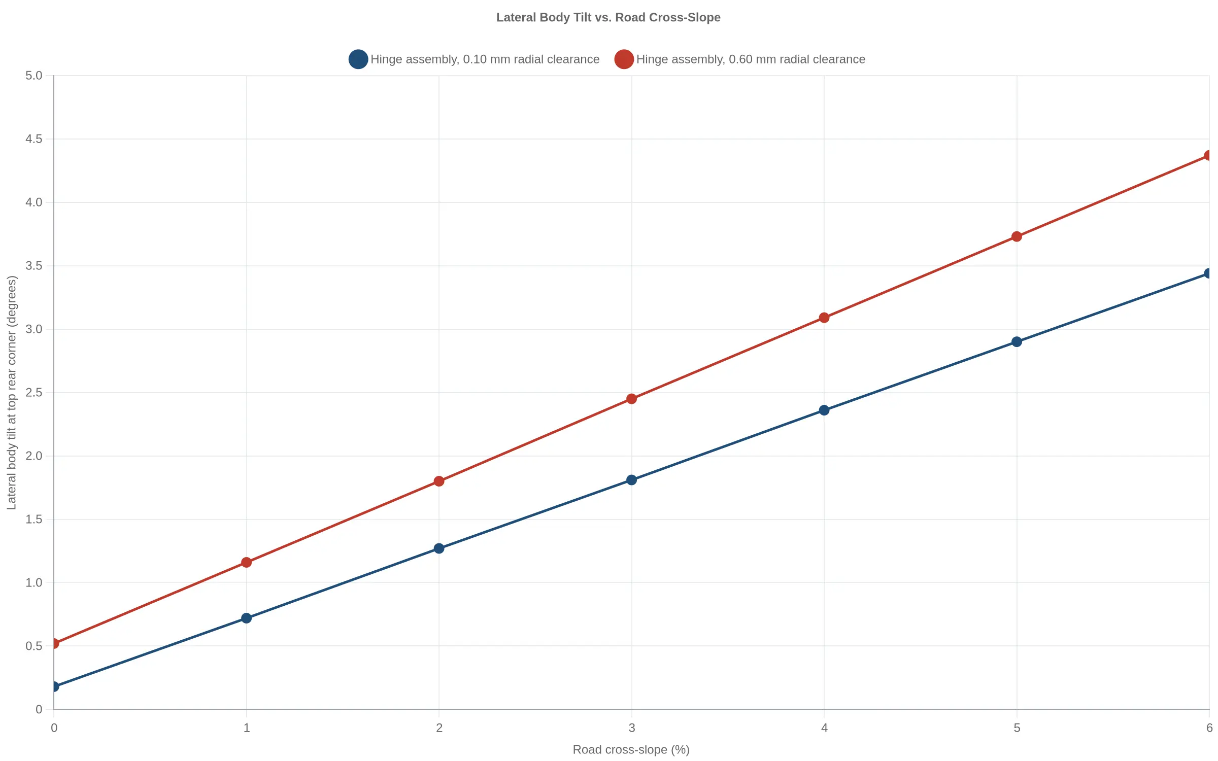
Lateral tilt measured at the top rear corner of the raised body, plotted against road cross-slope. Geometric assumptions: the hinge axis is treated as a straight line parallel to the frame rails, 1.10 m below and 0.40 m inboard of the top rear corner of a 4.0 m raised body; chassis roll is taken as arctan(cross-slope); hinge free play is estimated as the radial clearance at both bosses divided by an effective 0.35 m lever arm, then amplified by a factor of about 4 through the cylinder pair geometry; the body is treated as rigid and the lift cylinders are assumed not to correct lateral roll. Values are from a simplified rigid-body kinematic model, not from test data – use the curves to judge the magnitude of the clearance effect, not as a pass/fail specification. The residual tilt on the 0.10 mm curve at zero crown (about 0.2 degrees) belongs to the model’s simplifications rather than to any truck; read the separation between the curves, not their height.
| Cross-slope (%) | Road roll, arctan (deg) | Body tilt, 0.10 mm clearance (deg) | Body tilt, 0.60 mm clearance (deg) |
|---|---|---|---|
| 0 | 0.00 | 0.18 | 0.52 |
| 1 | 0.57 | 0.72 | 1.16 |
| 2 | 1.15 | 1.27 | 1.80 |
| 3 | 1.72 | 1.81 | 2.45 |
| 4 | 2.29 | 2.36 | 3.09 |
| 5 | 2.86 | 2.90 | 3.73 |
| 6 | 3.43 | 3.44 | 4.37 |
Reading the Curves in the Workshop
- The vertical gap between the lines is the wear signal. At a flat 0 percent pad the two curves already sit 0.34 degrees apart, and by a 6 percent crown the gap has grown to 0.93 degrees. On the body modelled here, whose top rear corner sits 1.10 m above the hinge axis, that upper figure is roughly 18 mm of lateral drift at the corner – enough for a spotter to call out, and enough to side-load a ram.
- A tight hinge mostly tracks the road. With 0.10 mm of radial clearance the body tilt stays within about a fifth of a degree of true road roll, and the gap narrows as the crown steepens. That is why the truck looks level against the crown and the operator feels nothing odd.
- A loose hinge adds lean of its own. At 0.60 mm – past the reject limit this guide uses, though plenty of crews call that “acceptable slop” – the body leans 0.5 to 0.9 degrees further than the road, and the extra lean is not linear: it steepens as the crown increases, because the worn bosses let the body rotate about a shifting contact point.
- Measure before you condemn the hydraulics. If the body lifts crooked to the same side on flat ground, that is clearance, not cylinder phasing. Compare your bush measurement against published hinge pin wear limits on rear-loader compactor bodies before ordering rams you do not need.
Numbered Procedure: How to Measure Hinge Pin Wear Before the Assembly Binds
When a tipper or rear-loader body starts climbing crooked on a crowned road, the hinge pin is almost always further gone than the operator thinks. The drill below is the sequence for measuring hinge pin wear properly – pin, bushing, straightness and lug alignment – so the problem is caught while it is still a number on a sheet rather than a seized joint on a route morning. Work through it in order; each step depends on the one before it.
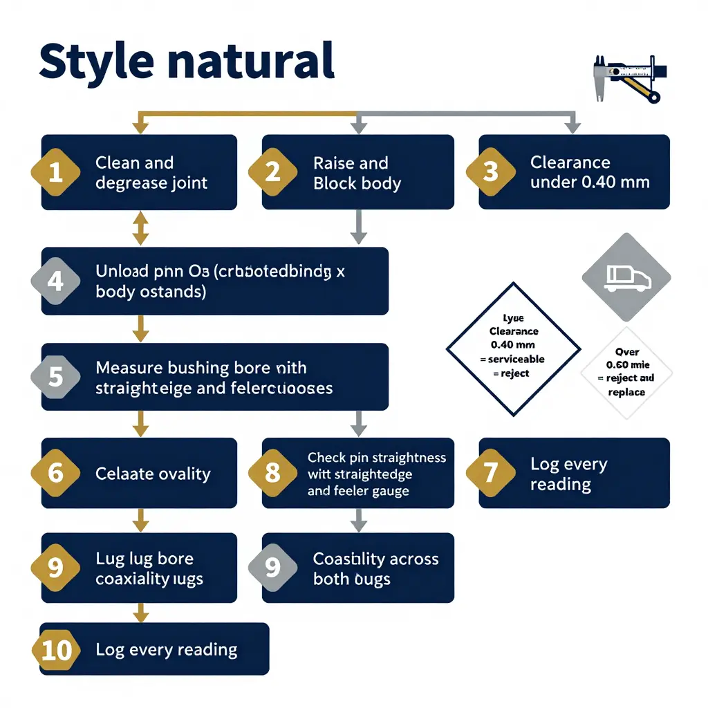
The Ten Steps
- Clean and degrease the joint. Steam-clean or solvent-wash the hinge area, then scrub the pin ends, bushings and lug faces with a wire brush until bare metal is visible. Grit, dried grease and road film add tenths of a millimetre to every reading and will ruin a micrometer’s anvil seating. Dry the joint fully before measuring.
- Raise the body and mechanically block it. Lift the tipping body with the hoist, then lower it onto rated stands or hardwood blocking placed under the frame rails – never rely on the hydraulic cylinder alone. Lower the pressure and isolate the pump. A body that settles mid-measurement is a crushed-hand event.
- Unload the hinge before measurement. With the body resting on the blocking, confirm the pin carries no load: the lugs should be free of contact pressure and the pin should rotate or slide with hand effort. Measure a loaded hinge and you will read a distorted bore, not a worn one.
- Measure the pin outside diameter at four circumferential positions and three longitudinal stations. Using an outside micrometer (or a calibrated digital caliper where access is tight), record the OD at 0°, 90°, 180° and 270° around the pin, repeated at three stations along its length – front, centre and rear of the bushing contact zone. That gives twelve readings per pin. Mark the pin ends so you always know which face is 0°.
- Measure the bushing bore. Use a telescoping gauge and micrometer, or a dial bore gauge set to the nominal bore. Rock the gauge to seat it on the true diameter, then read at the same three stations. If the bushing is scored or has a step, take the bore reading at the wear track, not at a clean unworn land.
- Calculate radial clearance. Radial clearance = (bushing bore − pin diameter) ÷ 2. Work from the worst-case combination: the largest bore against the smallest pin diameter at the same station. This single figure sets your radial clearance tolerance decision, because clearance – not pin size alone – is what lets the body rock and lift unevenly.
- Calculate ovality. Ovality = maximum diameter − minimum diameter, computed separately for the pin and for the bore. Anything above about 0.05 mm on a serviceable pin or 0.10 mm in a bush means the joint is hammering rather than rotating, and new bushes will wear out fast against a pear-shaped pin.
- Check pin straightness. Lay a straightedge along the length of the pin and try a feeler gauge in the gap at the centre and at each end. Any gap above roughly 0.10 mm indicates a bent pin – replace it, because a bent pin loads one lug and accelerates bore wear on that side only.
- Check lug bore coaxiality across both lugs. With the pin withdrawn, run a straight bar or laser alignment tool through both lug bores and measure the offset at the far lug. Misalignment over about 0.20 mm, or visible eccentricity in the bore, points to a distorted or cracked lug – the failure mode that turns a crooked lift into a torn hinge bracket. For the wear signatures that precede this stage, see the notes on hinge pin wear on rear-loader compactor bodies.
- Record every reading on a per-hinge-point log sheet. Log truck unit number, date, hour meter, hinge position (left or right), all twelve pin OD readings, all bore readings, calculated clearance and ovality, straightness gap and coaxiality offset, plus the technician’s name. Trend the numbers across services – a joint gaining 0.05 mm of clearance per 1,000 hours is telling you when to schedule the change-out.
Indicative Limits at a Glance
| Joint condition | Radial clearance | Action |
|---|---|---|
| New / as-built | 0.05 to 0.15 mm | Baseline reading, log it |
| Normal service | up to 0.25 mm | Monitor at each service |
| Watch zone | 0.25 to 0.40 mm | Plan bush replacement, re-torque and inspect monthly |
| Service limit | around 0.40 mm | Replace bush and pin at the next workshop window |
| Reject | beyond roughly 0.60 mm | Do not tip the body; replace pin and bushes before further use |
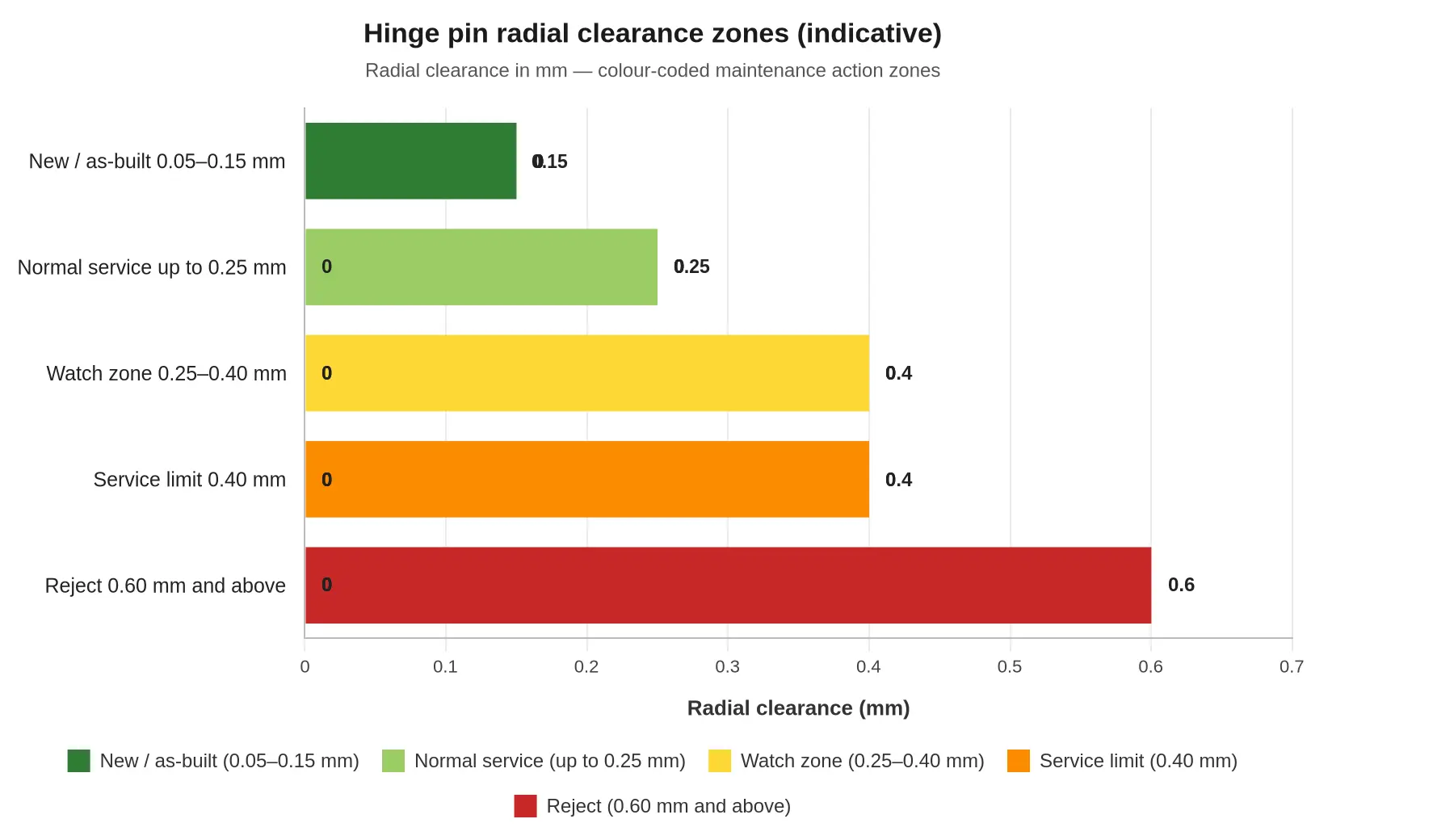
Important: the figures above are indicative shop-floor guidance for heavy truck tipping hinges, not a specification. The manufacturer’s specification for your chassis and body always overrides these numbers – where the OEM book calls for a tighter limit, or a different measuring datum, follow the book. Record the OEM limit you are working to on the log sheet so the next technician measures against the same yardstick.
Done in this order, the procedure takes about an hour per hinge point – most of it cleaning and blocking – and gives you a defensible answer: adjust, monitor, or replace. That beats discovering the truth with a crooked body halfway up the ram.
Where to Take Hinge Pin and Bushing Readings
Before you blame the hydraulic circuit for a body that lifts crooked on a crowned road, put a number on the hinge. The diagram below shows the four stations that matter on the pin-and-bushing pair: 0, 90, 180 and 270 degrees around the pin circumference, with the dashed concentric circle representing the worn bushing bore offset from the pin centre.
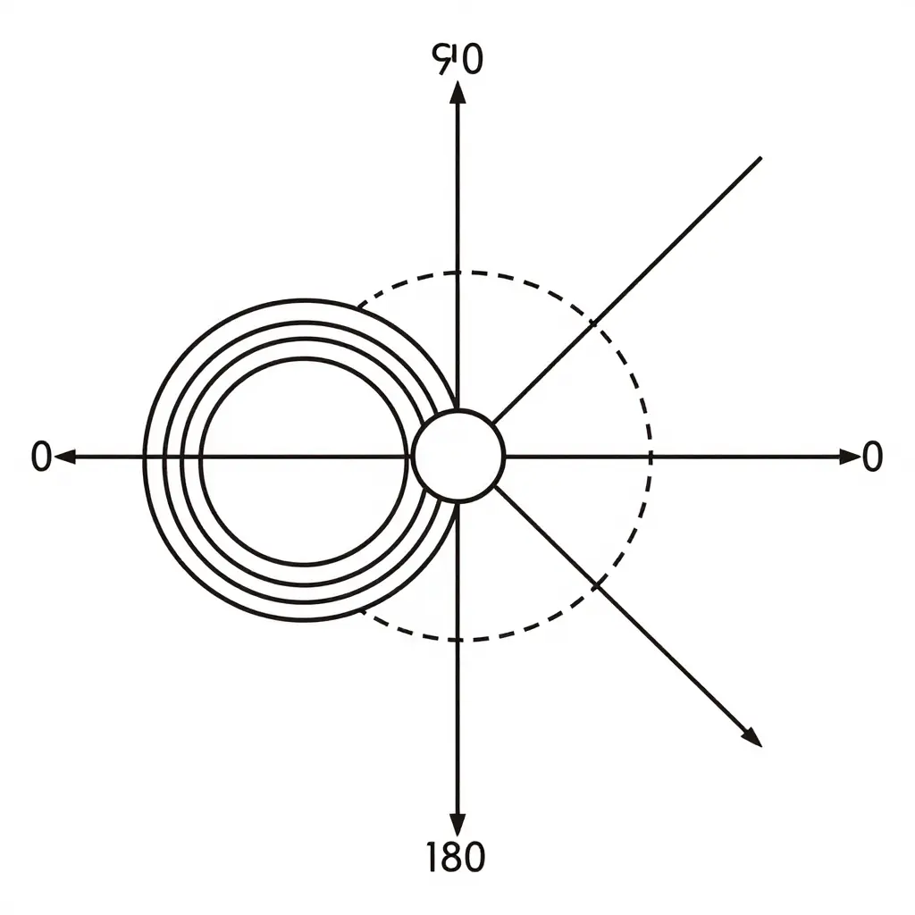
Readings for pin diameter and bushing bore are taken at the same four clock positions – 0, 90, 180 and 270 degrees – around each component. Using identical stations on both pin and bore lets you subtract one from the other at the same point, so ovality and radial clearance can be compared directly instead of being inferred from a single diameter.
Reading the Four Stations
The vertical pair (0 and 180 degrees) carries the load on a tipper hinge, so wear usually shows there first. The horizontal pair (90 and 270 degrees) is your control – on a healthy assembly those two readings should match the vertical pair within a few hundredths of a millimetre.
| Station | What you record | What it tells you |
|---|---|---|
| 0 deg (top) | Pin diameter and bore diameter at the same angular position | Loaded zone wear; first place a pin goes oval |
| 90 deg | Pin diameter and bore diameter at the same angular position | Side control reading; confirms measured ovality |
| 180 deg (bottom) | Pin diameter and bore diameter at the same angular position | Opposite loaded zone; combined with 0 deg it defines pin ovality |
| 270 deg | Pin diameter and bore diameter at the same angular position | Second control reading; cross-checks the bore offset direction |
Take each pair with a micrometer on the pin and a bore gauge or inside micrometer on the bushing, and write the numbers down at the time of measurement. A pin that is round but undersized is a wear problem; a pin that measures differently between 0 and 90 degrees is an ovality problem, and it will let the body lean long before the joint visibly rattles.
For the wear limits and the failure sequence these readings feed into, see our guide to rear loader hinge pin wear before you order parts.
From Numbers to Decisions: Repair and Return-to-Service
A worn hinge pin is never the real problem – what that clearance does to the lift path is. Once you have recorded pin diameter at four points, bushing ID, bore ovality and axis offset, the numbers should point to exactly one repair route. The table below is the decision gate the shop floor should work from before anything is disassembled.
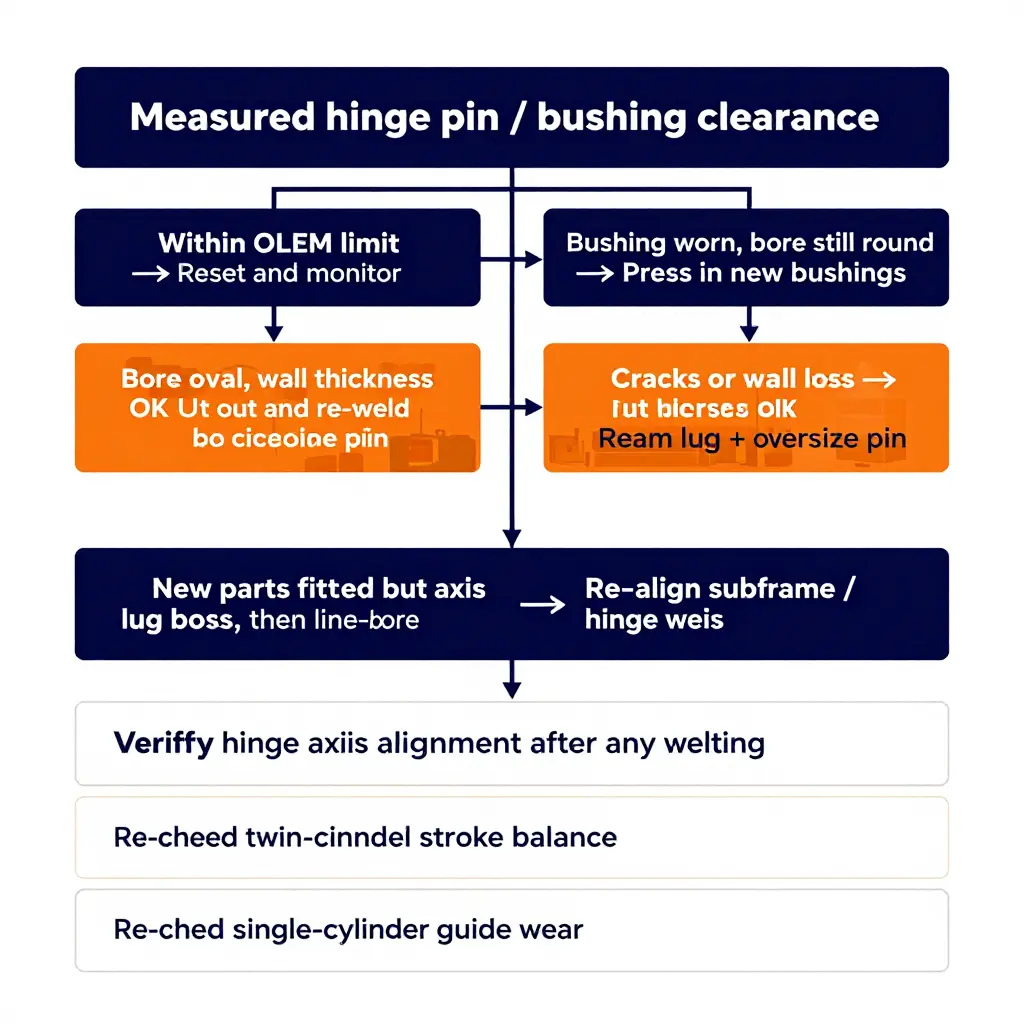
Decision matrix: what each measurement tells you to do
| Measured condition | Typical trigger value | Correct action |
|---|---|---|
| Clearance within OEM range, bore round | 0.10 – 0.35 mm radial (check OEM spec) | Clean, re-grease, monitor at next service |
| Bushing worn, lug bore still round | Bushing ID worn 0.5 mm+ over nominal, bore ovality under 0.10 mm | Press in new bushings only |
| Bore oval, boss wall intact | Clearance 0.60 – 1.20 mm, ovality 0.20 – 0.50 mm | Ream lug, fit next oversize pin |
| Bore already at second oversize or badly oval | Ovality over 0.50 mm, or two oversizes used | Cut out and re-weld the lug boss |
| Cracks radiating from the bore | Any crack, or wall loss over 10 percent | Cut out and re-weld the lug boss |
| New pin and bushing fitted, body still lifts crooked | Axis offset or twist measurable | Re-align subframe / hinge axis |
When to ream the lug and fit an oversize pin
Reaming is the right call when the bore is oval or slightly oversized but the boss still has wall to give. Line-bore the lug on a bar – never hand-ream – and hold bore concentricity to about 0.05 mm across the full length of the lug. Step up in 0.5 mm increments, keep the reamed bore round and parallel, then hone to the OEM surface finish so the new bushing seats with proper crush. If the boss has already taken two oversizes, stop: there is not enough material left to carry the shear load.
When to press in new bushings
If the pin is within wear limits and the lug bore is still round and at nominal size, only the bushing is worn. Press bushings in with a driver on the outer race, never with a hammer, and confirm installed ID after pressing – a bushing that closes up 0.05 mm on installation will not hold clearance. Anything that has to be heated to go in will come loose later.
When to cut out and re-weld the lug boss
Cracking from the bore, wall loss beyond roughly 10 percent, a third oversize in demand, or ovality that no longer cleans up all point the same way. Gouge the old boss out, preheat per the chassis steel spec, weld with matched filler, allow controlled cooling, and then line-bore the new bore in place on the truck. A boss welded and drilled on the bench will be off-axis the moment it is installed.
When the subframe or hinge axis must be re-aligned
If a full set of new pins and bushings does not stop the crooked lift, the geometry is wrong, not the clearance. String-line or laser both hinge axes and compare parallelism over the full hinge length; check body twist at three points along the subframe. Bent subframe rails, a shifted body mounting pad or a racked frame all produce the same symptom – the body rolls to one side on a crowned road because it is already leaning before the cylinder strokes. The inspection sequence in these subframe and lift cylinder checks maps directly onto this diagnosis.
Matched sets, and the re-check after welding
Replace pins and bushings as a matched set, on both sides of the hinge. A new pin in a worn bushing simply transfers the clearance, and a mixed set on left and right guarantees a differential that reads as crooked lift. Verify axis alignment after any welding – arc distortion moves a bore, and a re-weld without re-measurement is an unfinished repair. Re-check parallelism, bore position and installed clearance before the body is cycled under load.
Re-check the hydraulic side once clearance is corrected
Mechanical slop masks hydraulic faults, and correcting the slop exposes them. With the hinge tight, re-check twin-cylinder stroke balance by measuring rod extension on both cylinders at the same point in the stroke under the same load; a differential over about 5 mm – the sign-off limit used below – points to internal bypass, a bent rod or unequal mounting geometry. On single-cylinder tipper bodies, re-inspect the guide and wear ring for scoring and side-load, since a tight hinge changes how the cylinder is loaded. If the lift is also slow or stalls on cold mornings, the faults overlap with the pressure and flow checks in why cold morning lifts stall.
Explicit return-to-service criteria
Do not sign the truck off on feel. Release it only when all of the following are measured and recorded:
- Radial clearance at both hinge pins within OEM maximum, and left-to-right difference no more than 0.15 mm.
- Bore ovality under 0.10 mm, and installed bushing ID inside nominal tolerance.
- Hinge axis parallelism within 1.5 mm over the full hinge length; no measurable body twist across the subframe.
- After welding: dye-penetrant clean, weld toe ground, bore line-bored and re-measured in place.
- Twin-cylinder stroke difference 5 mm or less at mid-stroke and full extension under rated load; no rod drift in a 10-minute hold.
- Cylinder guide and wear ring free of scoring; no side-load visible on the rod.
- Full-raise test on a crowned surface: body cross-tilt under 1.5 degrees, with no binding, chatter or cylinder hesitation through the stroke.
Anything that fails one of these numbers goes back on the jack stands – not back on the route.
FAQ: Crooked Tipping and Hinge Pin Limits
These are the five questions that come up most often when a body lifts off-centre or a hinge starts to bind. Every figure below is a measurement you can take today with a digital inclinometer, a telescoping gauge, or a grease gun.
How much lateral tilt is acceptable during a raise?
Up to 2 degrees of cross-body tilt is acceptable at any point in the stroke. Zero a digital inclinometer on the chassis frame and read the body floor at the front bulkhead. Past 3 degrees at mid-stroke, stop the raise and check pin-to-bushing clearance and cylinder synchronization before the next lift. Drift beyond 2 degrees to one side on flat ground is a wear or geometry fault, not a road problem, and the sign-off figure in the return-to-service list above is tighter still at 1.5 degrees on a crowned surface.
Can a tipper garbage truck be tipped safely on a crowned road?
Yes, inside the tilt allowance. A typical 2% crown equals roughly 1.1 degrees of cross-slope, which fits within the 2-degree window. Keep total cross-slope under 3 degrees: park with the hinge axis across the crown rather than along it, and pack the low-side rear wheels before raising. At 5% crown (about 2.9 degrees, close to that ceiling) or more, relocate the truck instead of tipping.
What greasing interval protects hinge pins from binding?
Grease the hinge pins and bushings every 250 operating hours or every two weeks, whichever comes first. Leachate-exposed refuse duty cuts that to 100 hours. Use a lithium-complex EP grease and verify old grease purges from every seal; a pin that stops taking grease is already binding. Pair the interval with a clearance check – see these hinge pin wear tolerances for rear-loader bodies – so the grease schedule and the wear limits stay on the same worksheet.
Can worn hinge pins damage the lift cylinder?
Yes. At 1.5 mm (0.060 in) of diametral pin-to-bushing clearance the body shifts off-axis and side-loads the rod. Rod scoring, seal weeping, and gland wear follow. Replace pins before clearance reaches 2 mm. Resealing a cylinder on a worn hinge repeats the same leak within a few months.
Should pins and bushings always be replaced together?
Yes. Replace as a set when bushing ID wear exceeds 0.5 mm over nominal or out-of-round passes 0.25 mm. Measure with a telescoping gauge at the 12 o’clock and 6 o’clock positions. A new pin pressed into a worn bushing keeps the clearance you just paid to remove, and the joint re-binds inside one season.
Maintenance Schedule and Inspection Summary
The whole inspection programme rests on three tiers: a frequent greasing and visual check that catches looseness and dry joints early, a periodic full pin and bushing measurement that turns “it looks fine” into numbers on a sheet, and a short list of measured conditions that end the conversation and take the truck out of service.
| Interval | Task | Pass or fail criteria |
|---|---|---|
| Every shift, pre-trip | Grease every hinge and tilt-cylinder pin; visual check of hinge ears, keeper plates, retaining bolts, wear pads and hydraulic lines | Pass: grease taken at every nipple, no fresh weld cracking or fretting dust. Fail: missing retainer, weeping line, or a pin that has begun to walk |
| 250 operating hours or monthly | Re-grease with the body down, check hinge bolt torque, raise the body on a level pad and on a crown and compare both sides | Pass: even rise on both surfaces. Fail: one side trailing by more than a hand’s width, or the body settling to the crowned side on the way down |
| 1,000 operating hours or quarterly | Check pin rotation with the body raised and mechanically blocked, bushing end-float, wear pad thickness and shim stack | Pass: pin rotates by hand, end-float within spec. Fail: pin frozen in the bushing, wear pads below minimum thickness |
| 2,000 operating hours or six months | Full pin and bushing measurement: pin diameter in three planes, bushing bore, running clearance, ovality, hinge ear hole elongation | Pass: every reading inside the manufacturer’s published limits. Fail: any single reading outside them |
| Annually, or after any impact or overload | Structural inspection of the hinge mount, cross-member and frame rails, including a close look for hidden frame rail cracks | Pass: no cracking, no witness marks at bolt heads. Fail: any crack indication or bracket movement |
Measured Conditions That Trigger Immediate Out-of-Service
- Running clearance between pin and bushing measured above the manufacturer’s limit for the joint.
- Pin diameter worn below the minimum, or more than roughly 0.3 mm spread across the positions and stations measured above, indicating oval wear.
- Visible cracking in a hinge ear, gusset or mount plate weld, or elongated hinge bolt holes with movement witness marks around the bracket.
- Body tipping measurably to one side when raised on a level pad, or a pin that binds, groans or seizes during the lift.
- A bent or scored tilt-cylinder rod, or a pin showing heat discoloration from running dry.
These trucks are built under CRRC’s quality system with specified hinge clearances, which is why the manufacturer’s limits, not a workshop rule of thumb, should be the reference point for every measurement above. Keep the readings on file: a clearance that is legal today and 0.2 mm wider next quarter tells you more than any single inspection result.