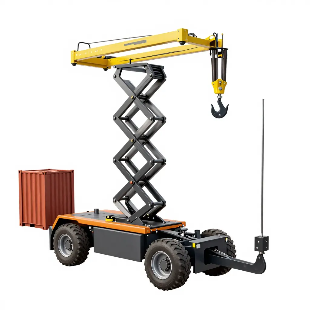
Why Bins Land Off Angle on Sloped Curbs
A bin that sets down twisted, one corner of the lip on the curb before the rest, is usually a geometry problem first and a wear problem second. A swing arm skip loader does not lift a bin in a straight line. The arm swings it along an arc, and the pivot point fixes that arc. The bin cannot follow the curb; it follows the arc.
Sloped curbs are where this shows up most often, because a gradient tilts the ground reference the arm was set up against. The slope does not create the error, though. It exposes it. The error itself usually sits at the pivot bushing: as wear opens the clearance between pin and bore, the arm begins its swing from a slightly different centre, and the length of the arm multiplies that shift. Move the pivot two millimetres and the touchdown point at the lip can move much further.
That is why worn pads, a stop adjustment or a shim in the bin saddle rarely hold for long. All three sit downstream of the geometry. The pivot is where the error starts.
Correct the pivot before anything downstream: it sets the arc, and the arc decides where the lip touches down.
The checks below follow that order: pivot geometry first, then bushing and pin wear, then the arm, the stops and the bin.
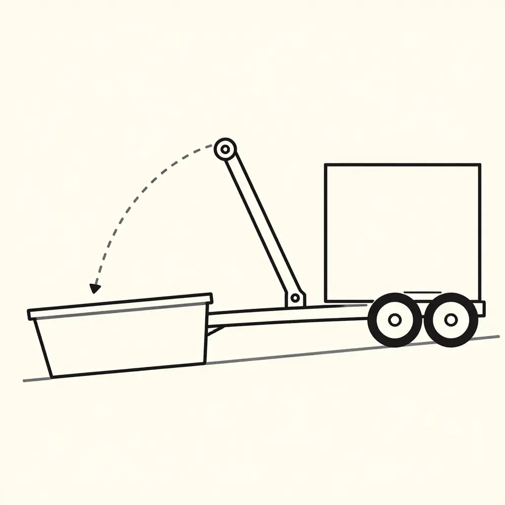
The rectangle at the lower left is the bin, the inclined line under it is the curb grade, and the ringed dot on the chassis is the single pivot the arm rotates around. The dashed curve runs from raised to set-down, and the gap between the bin base and the ground line is where an off-angle landing comes from. The same jib-and-geometry logic is worth a look when you check jib angle and rear axle load on soft ground, because the cause chain is nearly identical.
How a Sloped Curb Changes the Landing Angle
A swing arm skip loader sets a bin down along an arc built around a level ground reference. The arm sweeps through a fixed rotation, and when the sweep ends the bin base sits parallel to the datum the geometry was designed against. Put the truck on a sloped curb and the ground tilts; the arc does not. It still delivers the base to the level plane it was built for.
So the bin lands on one edge. The downhill edge reaches the pavement first and the rest of the base stays up in the air. From the cab the bin looks seated. Measured at the curb, the landing angle is off by roughly the slope of the ground, plus whatever the arm and the base add on top of it.
Three factors decide how much of that error actually shows up:
- Curb slope. A gentle 2% crossfall opens a small gap. A steep apron or a rolled curb can hold the uphill face up by several centimetres and load one edge of the base hard.
- Bin base flatness. A flat, straight base contacts cleanly along one edge. A bowed or dented base touches at a single point, so the gap opens unevenly and the bin rocks.
- Pivot position accuracy. The arc origin is only as good as the pivot itself. Worn bushings and pin play shift that origin, which is one reason bins stop halfway through the tipping arc even when the hydraulics are healthy.
All three add up, which is why a bin that lands flat in the yard can still sit visibly tilted at a curb with a modest grade. The inspection list below gives the measurements to take at each point, in the order they are quickest to check.
Clearance Is the Number to Watch
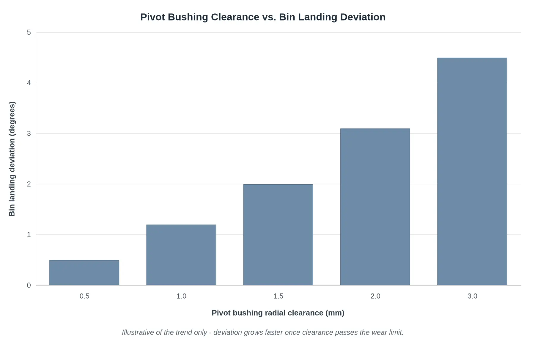
Before you blame the curb, measure the play. The figures below show how landing deviation grows as radial clearance at the pivot bushing opens up. At 0.5 mm it is about half a degree, at 1.5 mm about two, at 2.0 mm just over three, and by 3.0 mm it is around four and a half. Somewhere in that range a bin that used to settle square starts landing on a corner and skating sideways on a sloped curb.
| Pivot bushing radial clearance (mm) | Bin landing deviation (degrees) |
|---|---|
| 0.5 | 0.5 |
| 1.0 | 1.2 |
| 1.5 | 2.0 |
| 2.0 | 3.1 |
| 3.0 | 4.5 |
Caption: Illustrative of the trend only – deviation grows faster once clearance is past the 1.0 mm wear flag.
The wear table further down sets the flag at 1.0 mm of radial clearance and replacement at 1.5 mm. That reading is worth taking every few hundred lifts and at every service, rather than trusting a set-down that looks level. If bins are already arriving with beaten-up lips and bent contact pads, the wear is feeding itself – see what bin lip wear tells you about the rest of the lift cycle before you fit new bushes.
Field Inspection Sequence Before Adjusting the Arm or Bin
Work through these checks in priority order, and record every number before touching a stop, a linkage or a flow control.
- Check pivot bushing play and radial clearance first. Lock out the hydraulics, park the arm in its rest position, and measure radial clearance at the pivot with a dial indicator. Pivot bushing wear is the single most common cause of an arm that lands out of level, so compare the reading against the manufacturer’s limit before anything else.
- Inspect the pivot pin and boss bore. Measure the pin diameter at the worn bands against an unworn section, and gauge the boss bore with a telescopic gauge. Note scoring, ovality or fretting marks that would let the arm shift under load.
- Verify the arm stop and set-down position. Lower the arm onto a flat concrete pad and measure the gap at the stop pad with a feeler gauge. Both sides should contact evenly, with the arm resting square rather than hung on one corner.
- Check bin base flatness and lip condition. Run a straight edge across the bin floor, then measure the lifting lip thickness and straightness. Note dents, rolled lips or a bowed base that tilts the bin as it settles.
- Confirm curb slope at the collection point. Take a digital level reading across the actual pick-up spot and record the cross-fall percentage. Compare it against the flat pad reading so slope error is separated from machine error.
- Review hydraulic set-down speed for slam effect. Time each set-down with a stopwatch and watch the last 200 mm of travel. A fast final drop masks position error and pounds the pivot, so check the lowering cushion and the flow setting against the subframe and lift cylinder checks used on similar bodies.
- Repeat the set-down on level ground as a control. Run the same cycle twice on the flat pad and compare lift-to-contact times and arm angle. A repeatable result puts the fault in the truck; a varying one points to the curb or the bin.
Log the readings before adjusting a stop, a pin or a valve.
Pivot Bushing Wear Checkpoints and Action Limits
Run these six checks on a level floor with the skip arm lowered and empty. A worn pivot rarely travels alone, and the same reading pattern usually shows up in hinge pin wear on rear-loader tailgates too.
| Checkpoint | How to measure | Action limit | Corrective action |
|---|---|---|---|
| Radial clearance at the pivot | Feeler gauge or dial indicator between pin OD and bushing ID, unloaded, at 12 and 3 o’clock | Flag at 1.0 mm (0.040 in); replace at 1.5 mm (0.060 in) | Fit new bushing, recheck clearance |
| Axial play at the bushing flange | Feeler gauge in the gap between flange face and bracket | Max 1.0 mm (0.040 in) total end float | Add shims or renew thrust washer |
| Pin diameter wear | Micrometer at three stations, 90 degrees apart, against nominal size | Max 0.5 mm (0.020 in) under nominal; out-of-round 0.10 mm (0.004 in) | Replace pin and hardware as a set |
| Boss bore out-of-round | Bore gauge or telescoping gauge on two axes, top and side | Max 0.15 mm (0.006 in) difference between axes | Bore and sleeve, or replace boss |
| Grease passage condition | Remove fitting, pump grease, watch for flow at both pin ends | Pass: grease exits both ends within 3 pump strokes | Clear with solvent and wire, fit new fitting |
| Bushing-to-bracket weld integrity | Visual plus dye penetrant or tap test along the weld toe | Pass: no crack, gap or rust bleed at the toe | Pull the truck from service, weld repair to procedure |
Record every reading at the same reference point and in the same truck attitude each service interval, so you are comparing trends rather than single snapshots. Write the date, the hours and who took the measurement next to each number, and re-measure any joint that has moved more than 0.2 mm since the last check.
What to Specify Before Ordering the Next Unit
If bins land nose-down on crowned pavement, or the arm drifts off level on sloped curbs, the cause usually traces back to the order sheet rather than the repair bay. When you brief a swing arm skip loader garbage truck manufacturer, these are the line items that decide whether the next unit behaves better than the one it replaces.
- Bushing material and wall thickness. Call out the bronze-backed or self-lubricating composite grade and a stated wall thickness, so there is real wear allowance between pin and bore instead of a thin shell that ovalises in a season.
- Hardened, ground pin with a replaceable sleeve. The sleeve takes the wear, so a rebuild means swapping a sleeve rather than line-boring the arm.
- Grease point count and service interval. Ask for the number of nipples per pivot and the recommended interval in hours. More points only help if your crew can actually reach them.
- Arm set-down geometry matched to typical curb conditions. Give the supplier your real curb heights and cross-slopes so the linkage is set to land bins flat on the ground you actually work, not a flat test pad.
- A factory measurement record for pivot clearance. A signed baseline clearance figure at delivery turns “it feels loose” into a number you can track.
Before the geometry is locked in, check bin size against chassis length: an arm working over a deck that is too short or too long fights its own arc from the first lift. If the lift cylinder and subframe are also being respecified, use the same subframe and lift cylinder checks to confirm the mounting points sit square to the arm.
Then keep a wear log at fixed intervals: monthly caliper readings at each pivot, with greasing recorded alongside. A clearance number that creeps rather than jumps tells you a sleeve is wearing, and you find it before a pin seizes or a bin lands crooked.
Pivot Bushing and Pin: What the Cutaway Shows
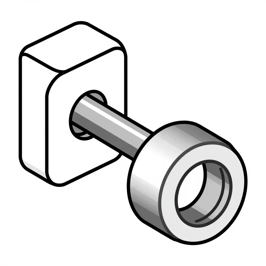
The bracket boss holds the bushing sleeve, the sleeve holds the pin, and the arm rotates on the pin. Three features in the drawing carry the diagnosis:
- The annular gap on one side is radial clearance. New, it should be a few hundredths of a millimetre. Once the bush has worn oval, the pin drops to the low side of the bore every time the arm lifts a bin.
- The crescent-shaped highlight is the worn zone. It is not symmetric, and that asymmetry is why bins land off angle on a sloped curb: the arm starts its arc from a slightly different position on every cycle.
- The arcs on the bushing wall are grease grooves. Dry or packed with grit, they let wear accelerate and the crescent grow faster than the maintenance interval suggests.
Set the drawing beside the clearance table and the inspection list, and the numbers stop being abstract. A 0.3 mm reading means the crescent has already started. The same wear pattern turns up on a rear-loader hinge, where hinge pin wear and what it does to cycle geometry follows a similar path.
FAQ: Off-Angle Landings and Pivot Bushing Wear
Why does my bin land off angle on a sloped curb even though the arm is level?
A level arm is level against the truck frame, not against the ground the truck is standing on. On sloped curbs one rear wheel often sits higher, which tilts the whole lifting plane, and the bin meets the ground at an angle instead of flat. Check pivot bushing wear before adjusting anything: play at the swing arm pivot lets the arm twist under load, and that twist adds to the curb slope, making an off-angle landing far worse than the ground alone would. If the bushing measures within the limit in the table above, the residual error is geometry, and it helps to understand how ground conditions change jib angle and rear axle load before you start shimming or re-rigging.
How much pivot bushing play is too much?
The wear limit in the table above is your pass/fail line: flag at 1.0 mm of radial play measured at the pin, replace at 1.5 mm. Below the flag, grease and re-measure at the next service. Above it, plan a bushing replacement before the arm starts loading the pin and the bore unevenly. The figures earlier in the article suggest how quickly the angle drift climbs once play passes the flag, which is why a trend matters more than any single reading.
Can a worn bushing be shimmed instead of replaced?
No. Shims correct axial end float, not radial play. A bushing worn oval still lets the arm rock sideways in the bore, so shimming the joint tightens the gap you can see and leaves the movement that causes an off-angle landing untouched. Replace the bushing, and measure the pin for step wear before you press the new one in.
How often should I grease and re-measure the swing arm pivot?
Grease at the OEM interval, which on most swing arm loaders means a few shots every 50 to 100 operating hours, and more often on wet or dusty routes. Re-measure radial play with a dial indicator at every major service, roughly every 250 hours, and record the readings so you can see a trend rather than a single snapshot. Trucks that work sloped curbs daily should be measured more often, because the pivot carries a side load there that flat-ground work never applies.
Does bin base flatness affect landing angle?
Yes. A bowed, dented or rusted-through base contacts a sloped curb at two high points and rocks, so the bin sets down tilted even when the geometry upstream is good. Check base flatness with a straightedge, but check pivot bushing wear first: it is faster, cheaper, and it is the most common single cause behind an off-angle landing.