Why the Lift Arm Slows When the Packer Runs
The packer and the lift arm draw from the same hydraulic pump. Whichever circuit gets oil first sets how fast the arm moves, and on most rear loaders that order is fixed when the valve block is laid out at the factory. On a China bin lifter garbage truck, the packer almost always sits ahead of the lifter, so the arm runs on whatever is left.
Three things combine to produce the slowdown:
- The pump has a ceiling. A gear or piston pump moves a set number of litres per minute at a given engine speed. Holding the lever harder does not change that.
- The packer cylinders take most of the output. Packer rams are large and push against compacted waste, so during a pack stroke they claim the bulk of the flow. Mid-stroke, very little is left for anything else.
- The valve ahead of the arm divides the remainder. A flow divider or priority valve upstream of the lift circuit fixes how much of the leftover volume reaches the arm. That split, not the cylinder and not the pump’s nameplate rating, is what the operator feels at the lever.
In practice the packer wins because it is plumbed first and holds its share for the whole stroke. The lifter gets the remainder.
If the arms crawl only while compacting and lift at normal speed with the packer idle, verify the split before replacing any component. A new pump or cylinder cannot add litres the valve was never routing to the arm. For the related symptom on the same circuit, see why bins stall halfway through the lift.
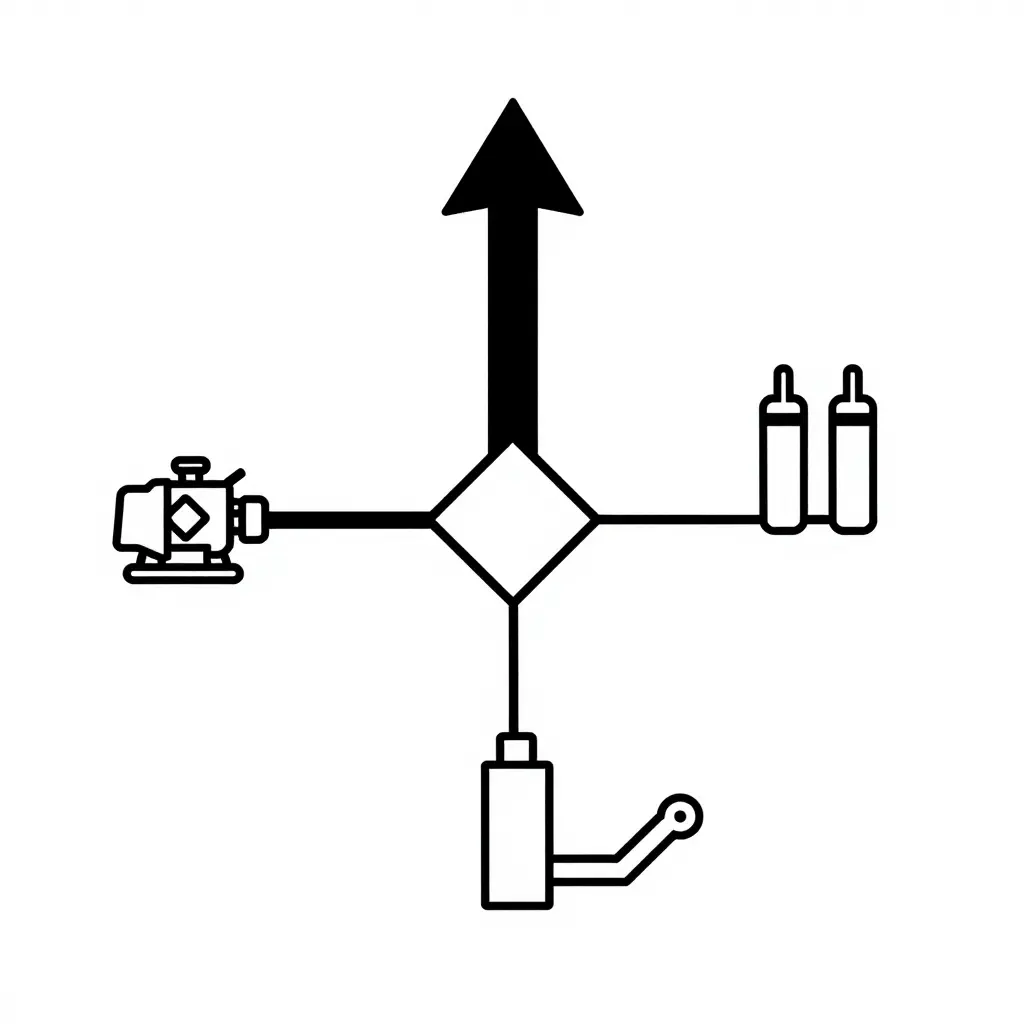
The heavy upper branch is the packer circuit taking the larger share of pump output. The thin lower branch is the lift arm circuit left with the remainder, which is why the arm crawls whenever the packer is working.
Flow Split Checks to Perform First, in Order
When a bin lifter slows down the moment the packer starts, the fault usually sits in the split between the two circuits rather than in the lift cylinder. Work through these checks in sequence and write down every number you measure, so you can tell which circuit is starving the other.
- Measure pump output at rated PTO speed against the displacement specification. Record actual flow in L/min at rated RPM and compare it with displacement multiplied by shaft speed. Low flow means a worn pump, internal slip, or a pump being driven too slowly.
- Confirm the PTO is at full rated speed, not partway. Log engine RPM and PTO shaft speed with the packer engaged. A slipping clutch pack or an idle-up fault leaves the pump turning slower than its flow rating assumes.
- Verify the flow divider or priority spool is not stuck or partly blocked. Note spool travel, binding, and any debris on inspection. A jammed spool sends the packer more than its share.
- Check the lift circuit relief setting and internal leakage. Record cracking pressure and any drop in hold position over 60 seconds. Oil escaping over a weak relief or past a worn seal looks like a split fault on the gauge.
- Inspect hose and fitting sizing on the lift branch. Note bore size, fitting type, tight elbows, and crushed sections. An undersized or pinched line throttles the arm exactly as a bad split does.
A timed comparison of the arm with the packer idle and running belongs in the same baseline; the flow-meter procedure later in this article covers how to take it. The table below maps what you observe to the likely cause.
If the arm still creeps halfway up on a wet, heavy bin, the fault may sit in the tipper linkage rather than the split, so it pays to read why bins stop halfway on a garbage truck before ordering parts.
Write the readings down before you change a part. A baseline of pump flow, relief pressure, and cycle time is what turns guesswork into a diagnosis.
Symptom-to-Cause Map for a Slow Bin Lifter Arm
| Observation | Most Likely Flow-Split Cause | Check to Run | Expected Reading |
|---|---|---|---|
| Arm slows only while the packer cycles | Splitter biased to the packer; arm circuit gets residual flow | Flow meter on the arm supply line, packer idle vs. cycling | Arm flow drop under 10%; at least 90% of rated L/min in both states |
| Arm slow in both states | Pump wear or relief set low, not the split | Stall briefly against the relief and read the gauge; compare to the pump tag | Relief cracking within 5 bar of spec; full rated flow at rated rpm |
| Arm speed drops as oil temperature rises | Internal leakage at a worn spool, worse as oil thins | Log cycle time at 30, 50 and 70 C oil temperature | Cycle time growth under 1.5 s across the range |
| Packer cycle also slows under load | Shared pump at its flow limit; both circuits undersupplied | Pump flow at relief pressure under load vs. no-load | Flow within 10% of rated at 150 bar |
| Arm stalls at mid-stroke | Spool not shifting fully; split valve stuck mid-position | Shift the spool by hand, measure flow past the valve | Full rated flow both directions; no leakage in neutral |
| Arm speed varies between units of the same build | Different pump displacement or relief settings between builds | Compare pump tag, relief setting and cycle time across units | Same displacement, relief within 5 bar, cycle times within 1 s |
If the arm stops part-way through the stroke rather than running slow, the same linked article covers the mechanical checks behind the hydraulics.
The Flow Divider, the Priority Valve, and Pump Displacement
A priority flow divider takes the pump’s total output and gives the lift circuit a fixed share first, then passes the remainder to the packer. That share holds roughly constant as packer pressure climbs, so the arm keeps its speed while the blade compacts. The limit is pressure: once inlet pressure approaches what the pump can deliver, the priority share falls away with everything else.
A plain tee does the opposite. It splits flow by resistance, so the packer’s load through the stroke decides how much oil the arm sees: while the blade moves freely, the packer is the easier path and the arm starves; once the blade loads up and packer pressure climbs past the lift pressure, flow swings back to the arm. Speed that changes with where the blade sits, and with bin weight, points at a tee rather than a divider. That is plumbing, not operator error, and an unfixed split explains most arms that slow only while the packer cycles.
A pump sized only for the packer makes it worse. If displacement is chosen to hit a target compaction cycle, no margin is left for the arm. Lock the hydraulic pump and PTO specification so both circuits get defined flow.
Total flow is pump displacement times drive ratio times engine speed. A taller PTO ratio can make up for a small pump, but only within the pump’s rated speed, torque, and cooling limits.
| Pump displacement | PTO ratio | Engine rpm | Approx. total flow |
|---|---|---|---|
| 40 cc/rev | 1.0 | 1500 | 60 L/min |
| 50 cc/rev | 1.0 | 1500 | 75 L/min |
| 40 cc/rev | 1.3 | 1500 | 78 L/min |
| 32 cc/rev | 1.0 | 1500 | 48 L/min |
The practical rule: the lift circuit needs its own stated minimum flow at packer operating pressure, not an average. Put that figure in the order, then confirm the valve reserves it with the packer fully loaded.
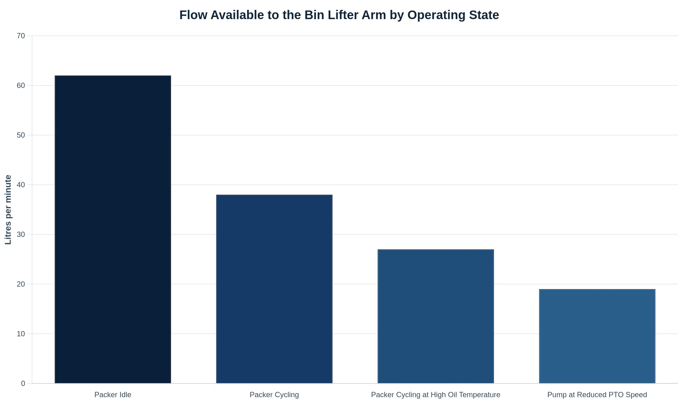
Flow to the lift circuit falls away the moment the packer starts drawing oil, and falls further with hot oil or a PTO running below rated speed.
How to Verify the Split With a Flow Meter and a Stopwatch
Before you blame the pump, show where the oil actually goes. A stopwatch, a clamp-on flow meter and a temperature gun turn “the arm crawls when the packer cycles” into numbers you can act on. Each step below narrows the list of suspects.
Step 1: Baseline the lift arm with the packer idle
Warm the oil to working temperature, park on level ground, and raise the empty lifter through a full stroke three times. Time each cycle from lever-in to full height and average them. That average is your baseline cycle time with the rest of the garbage truck hydraulic system at rest. Check the mechanical side while you are there: worn rollers, a bent linkage, or a worn bin lip can drag and mimic a flow shortage, so rule those out before opening any hydraulics.
Step 2: Repeat with the packer running
Run the packer at normal working speed and repeat the same three lifts. A cycle that grows by more than roughly 25-30% means pump output is being pulled away from the lift branch, the classic sign that the flow divider is not holding your circuit’s share under load.
Step 3: Install the flow meter on the lift branch
Fit a clamp-on or inline flow meter on the lift branch only, downstream of the divider and upstream of the valve. Read flow with the packer idle, then with it running. The idle figure is your available flow; the difference is what the packer is taking.
Step 4: Compare measured flow to what the cylinders need
Do the arithmetic rather than guessing. Required flow is bore area times stroke divided by cycle time, converted to L/min:
- 63 mm bore = 31.2 cm2, 60 cm stroke = 1,870 cm3 (1.87 L per full extension)
- A 6-second cycle needs 1.87 / 6 x 60 = about 18.7 L/min
- If the meter shows 12 L/min with the packer running, the lift is starved, and the divider is the first thing to check
Reading pressure at the lift relief while the arm is stalled
Hold the arm against its stop for no more than a few seconds, since long stalls cook the oil, and read the gauge at the lift circuit relief. A reading well under specification means oil is escaping past the relief or past the lift valve spool. Leakage shows up two other ways: heat and slow recovery. A leaking spool converts pressure into heat, so the valve body runs noticeably hotter than the return line after a stall test, and the arm sags or creeps back up slowly when you release the lever. If the arm also feels weak at the top of the stroke, work through these body lift issues before replacing parts.
Three readings to record
- Cycle time, packer idle (seconds, average of three)
- Cycle time and meter flow with the packer running (seconds, L/min)
- Stall pressure at the lift relief (bar), plus valve body temperature against tank temperature (deg C)
Those three lines, taken on the same warm afternoon, separate a divider problem from a worn pump, a leaking valve, or mechanical drag.
How the Priority Flow Divider Splits Pump Flow
The schematic below shows a lift-first priority valve, the arrangement worth specifying even though most trucks leave the factory with the packer first.
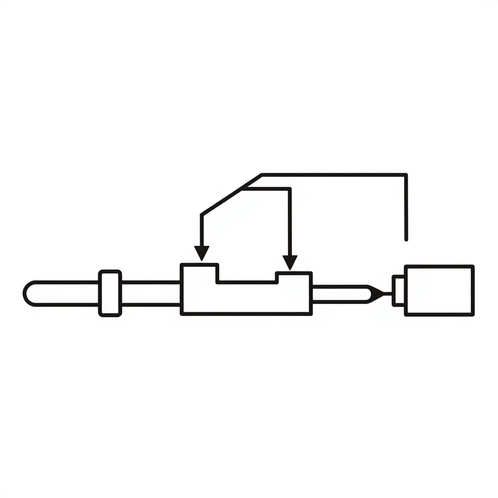
- Pump inlet feeds the spool bore.
- The spool sits in its lift-first position, so the bore opens the priority passage first and meters a fixed share of flow to the lift arm circuit.
- Whatever the lift circuit does not take spills past the second land and leaves through the bypass outlet toward the packer circuit.
- When the packer works hard, its pressure rises but the priority share stays roughly constant. That is the point of the design, and it is the first thing to verify when a bin lifter arm starts creeping instead of lifting.
If the arm still stalls after the split is confirmed, the next suspects are downstream of the divider, starting with the cylinder and linkage rather than the pump.
What to Write Into the Specification Before You Order
A slow lift arm is usually a specification gap rather than a design flaw. The pump, the packer circuit and the lift circuit are negotiating over the same oil, and the purchase order decides who wins. Fix the numbers on paper before the chassis is cut.
The six items that belong in the document
- Required lift circuit flow at packer operating pressure. State litres per minute available to the lift circuit while the packer runs at its rated working pressure, not free flow with the packer idle. This line forces the supplier to prove the flow split rather than describe it.
- Flow divider type and priority setting. Name the component: priority valve, proportional flow divider, or gear-type splitter. Give the priority percentage and the pressure at which it holds. Wording such as “priority to lift circuit” cannot be checked.
- Pump displacement and PTO ratio. Give cc/rev and the PTO-to-engine ratio, so rated flow can be verified against engine speed instead of assumed.
- Lift arm cycle time target. A load-to-tip-to-return figure in seconds with a stated bin weight, taken with the packer cycling.
- Oil cooling capacity. Heat rejection in kW at a stated ambient, sized for continuous pack-and-lift duty rather than a single lift demonstration.
- Acceptance test before shipment. Cycle the packer and the lift together, log pressure at both circuits and oil temperature, and photograph the gauges.
Minimum checklist to paste into the RFQ
- Lift circuit flow (L/min) at packer operating pressure, plus cycle time in seconds with a loaded bin
- Flow divider type, priority percentage and setting pressure, confirmed by model number
- Oil temperature rise logged during a 30-minute simultaneous pack-and-lift run, against cooler rating
If you are still settling body volume and arm reach, work through this sizing guide first so the hydraulic numbers land on the right chassis. Then use the supplier audit to check whether the factory can build to what you wrote. A truck that meets its cycle time on day one and loses it in year two was usually never tested properly at the bench.
Frequently Asked Questions
Can the lift arm speed be increased by raising the relief valve setting?
No. The relief valve caps maximum pressure, not flow, and cylinder rod speed depends on litres per minute entering the bore. Raising the setting only increases stall force and the risk of splitting a barrel or bursting a hose. If the arm is slow while the packer runs, the restriction is the split, not the pressure ceiling. Leave the relief at its specified value and measure flow at the lift cylinder inlet instead.
Does a larger pump alone fix the slowdown?
No. A bigger pump adds total output, but if that output feeds a priority flow divider still metering a fixed 15-20 L/min to the lift circuit, the arm gains nothing. The extra oil goes to the packer port and, when the packer is idle, over its relief back to tank as heat. The divider’s priority setting, the port and hose sizing, and the PTO ratio all have to be revisited, which is why the pump and PTO spec must be locked before build.
Should the packer be stopped before lifting a bin?
On most single-pump bin lifter garbage truck layouts, yes. The packer blade and the lift cylinder draw from the same pump, so overlapping the two cycles splits the available flow and the arm slows to a crawl or stalls halfway. Pausing the packer during the lift is standard practice, and a correctly set divider makes the overlap tolerable rather than marginal.
How much flow must be reserved for the lift circuit?
Enough to fill the lift cylinder at the speed your cycle time demands: typically 20-30 L/min for a 2-3 tonne lifter. Work it out from bore diameter, rod diameter and stroke against the target lift time, then set the flow divider priority port to that figure plus a 10 percent margin.