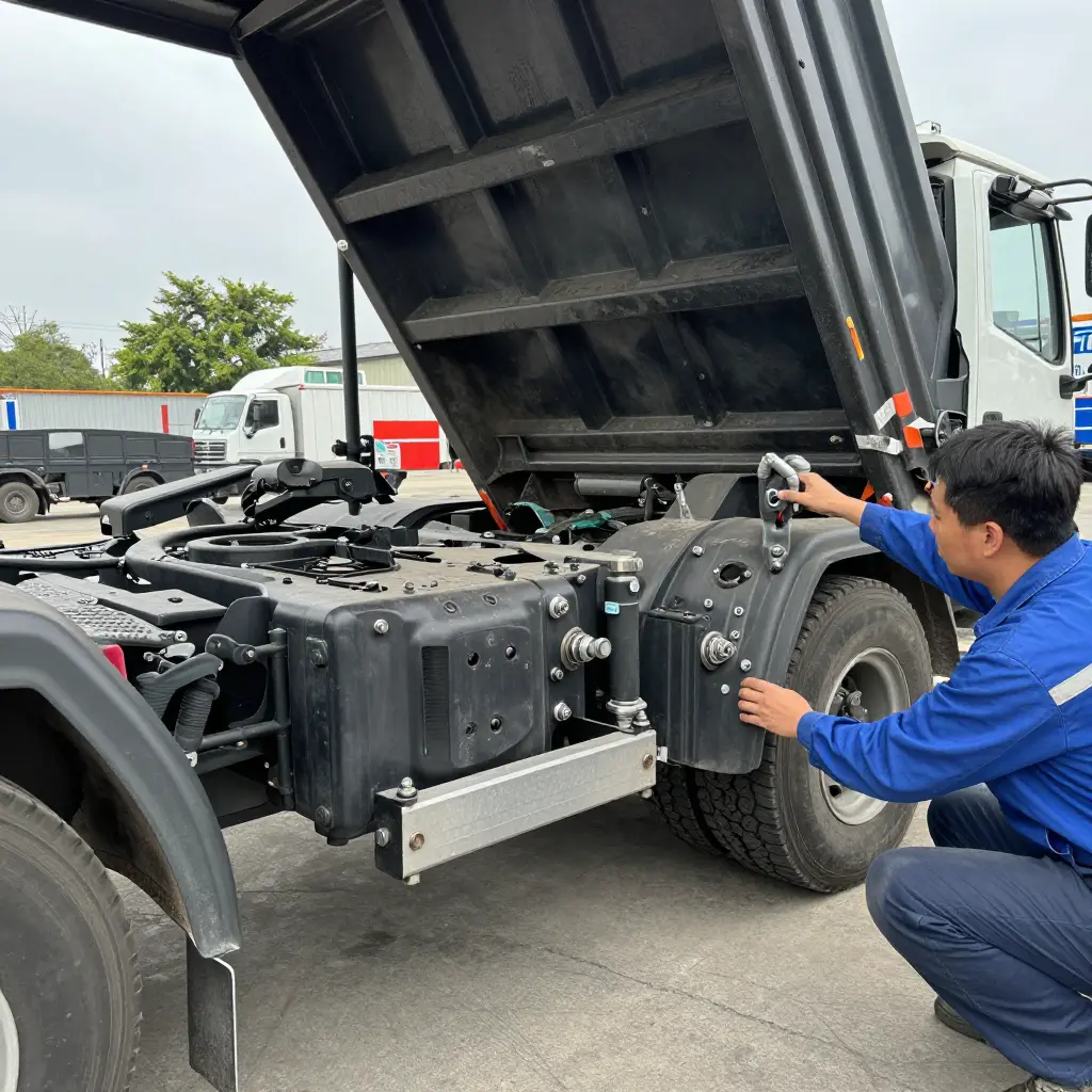
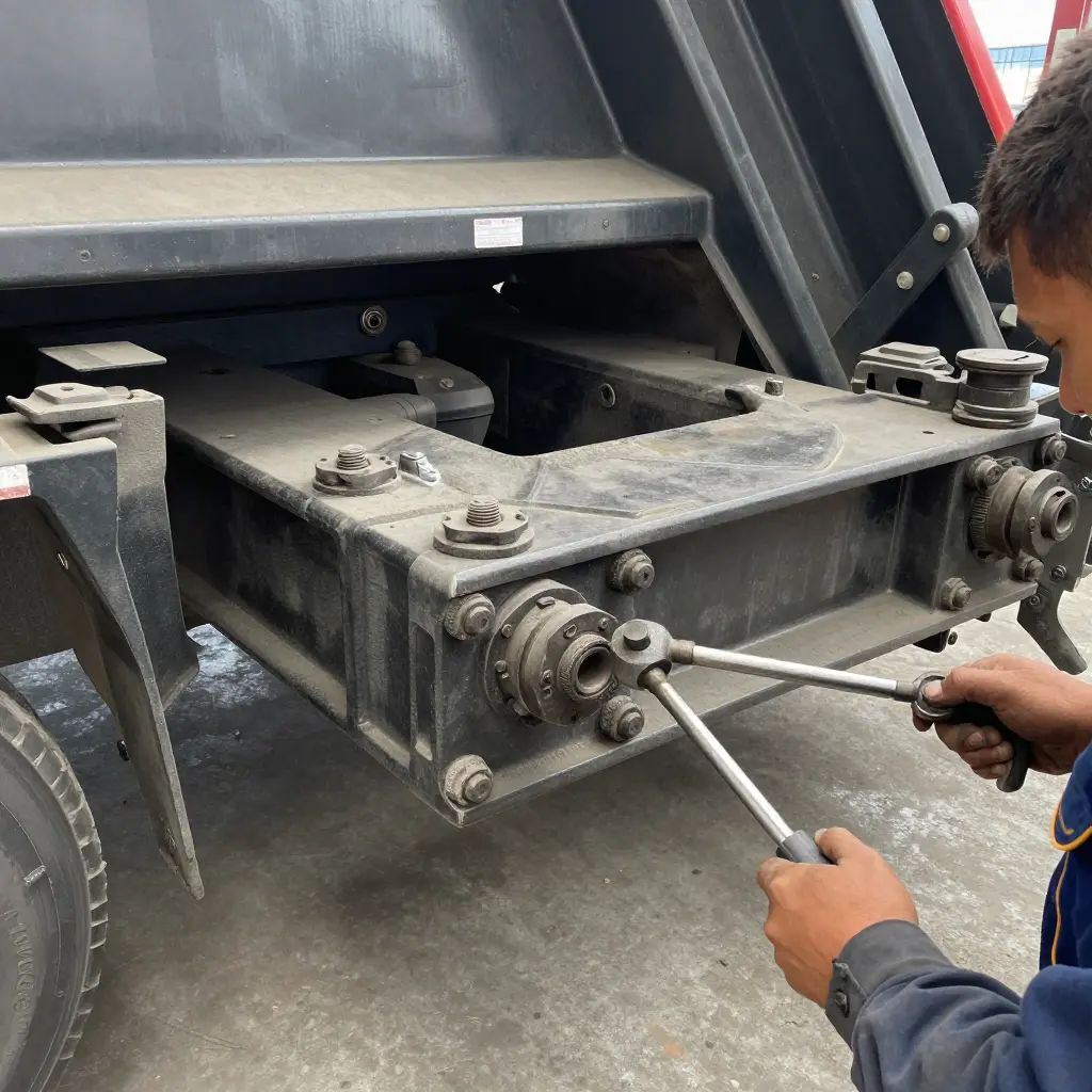
A tipper body never sits directly on the chassis frame. It rides on a subframe, and that subframe is clamped to the rails at a fixed set of mounting points. On a collection truck those joints take everything the route produces: wet refuse, potholes, kerb strikes, the roll of the truck leaning into a landfill slope. Load does not stop at the boundary between body and frame, so the joints have to be designed as one system.
Most mounting failures start at one joint and appear at another. A U-bolt loses clamp load, the subframe micro-slips, the pad at the next cross-member frets, the hole underneath it ovalises, and the first crack shows up a metre away from the fastener that started it. That is why body-to-chassis mounting decides whether the truck lasts years on hard collection work or starts cracking and losing hydraulic pressure in its first season.
A pre-delivery inspection works through the mounting system from front to rear:
- Mounting points: location, bracket condition, whether the body sits square on the frame.
- Fastener torque: correct grades, correct values, and a re-torque after the first loaded week.
- Cross-member spacing: spacing that matches body length and spreads load across both rails.
- Subframe contact: full, even contact pads instead of gaps that flex and fatigue.
- Hydraulic tie-in: pump, PTO and cylinder mounts kept clear of the body mounts.
- The sign-off sheet: pass or fail items recorded before the truck enters service.
If a body has already shifted or tips unevenly on the frame, read our notes on tipper body lift issues before ordering replacement parts. Every line below should be checked with a gauge, a torque wrench or dye penetrant rather than by eye, since frame rail faults are the hardest to catch later and show the same warning signs as the hidden frame rail cracks that turn up on used trucks.
Body-to-Chassis Mounting Checks: What to Verify and What Failure Looks Like
| Check Item | Where It Applies | Typical Failure on Rough Routes | Acceptance Criterion Before Dispatch |
|---|---|---|---|
| Frame rail flatness and straightness | Longitudinal rails, full length | Rail bow, twist, cracked flanges at cross-member joints | Max 3 mm per metre within any measured section, and no bow or twist beyond the drawing limit; no visible crack |
| Subframe-to-frame contact gap | Between body subframe and chassis top flange | Gap opening, fretting marks, loose mounts | 0.5 mm feeler gauge refused at every mount point |
| U-bolt clamp load and re-torque interval | U-bolts at spring seats and subframe clamps | Bolt stretch, thread galling, torque loss | Re-torque to spec at 500 km, then every 5,000 km or 30 days on rough routes; every value logged |
| Anti-vibration pad condition | Under subframe rails and cross-members | Compression set, cracking, oil swelling | Min 80% of original thickness; no crack over 5 mm; replace in sets |
| Cross-member spacing and reinforcement plates | Between longitudinal rails, gusset areas | Elastic flex, plate buckling, weld toe cracks | Spacing within 10 mm of drawing; plate gap under 0.5 mm |
| Body hinge and pivot alignment | Tailgate, tipper pivot and lift hinges | Pin wear, ovalised bores, offset binding | Pin-to-bore clearance within OEM range; hinge line offset 2 mm max |
| Hydraulic cylinder base and mount welds | Cylinder trunnion base, hoist frame brackets | Weld toe cracking, base plate lift, elongated holes | No linear dye-penetrant indication; base plate flat within 1 mm |
| Weld seam inspection at mounting brackets | All bracket-to-rail welds | Undercut, porosity, vibration toe cracks | No crack; undercut 0.5 mm max; leg length per drawing |
| Fastener grade and thread condition | Body-to-chassis bolts, U-bolts, bracket bolts | Grade substitution, stripped threads, corrosion seizure | Grade 8.8 or 10.9 as specified; full thread engagement; no damaged threads |
Log every reading and photograph each mount before the unit leaves the yard. A signed sheet with numbers on it is the only proof the body was fitted for a rough route rather than a smooth test loop.
Frame Contact and Fastener Torque
Clamp load holds the subframe on the rail, and the pad interface carries it. Refuse weight, hydraulic push and every bounce in a rough lane pass through those two things, so a joint built loose loads the frame rails instead.
Contact Area and Gap Tolerance
Aim for bearing along both rail flanges, not three or four high spots. After the first loaded week, at least 80% of each pad footprint should show even contact marking, and a 0.5 mm feeler gauge should not slide under any pad. A 1 mm gap is a defect, not a tolerance.
Gaps matter most at cross-member junctions and above the rear spring hangers, where bending stress peaks. Shim there with steel plate. Stacks of washers compress and work loose.
Pad Material Choices
| Pad material | Good for | Watch out for |
|---|---|---|
| Fabric-reinforced rubber | General tipper duty, vibration damping | Creep under sustained clamp load, re-check torque |
| UHMW polyethylene | Low-friction slip between subframe and rail | Cold flow; needs a steel backup plate |
| Steel shim / machined spacer | Closing gaps, restoring flatness | No damping, corrosion between faces |
| Hardwood block | Field repairs only | Compresses, dries, rots; replace quickly |
Why Clamp Load Beats Bolt Diameter
A clamped joint holds by friction between the faces, not by the bolt shank bearing on the hole wall. A well-lubricated, correctly torqued 20 mm U-bolt develops more clamp load than a 24 mm bolt tightened dry by feel. Bigger hardware with poor preload only makes a heavier joint that still slips.
When clamp load drops, the subframe micro-slips on the rail. That movement polishes the pad faces, grinds out reddish fretting dust and ovalises the mounting holes. Once a hole elongates, torque cannot recover the joint; the hole has to be bushed or the section repaired.
Thread Lubrication Changes the Result
Most of the wrench’s effort never reaches the joint. Roughly half of applied torque goes into under-head friction, about 40% into the threads, and only around a tenth becomes clamp load, which is why the same wrench setting with dry, oiled or anti-seize threads can land 25-35% apart in achieved clamp load. Name one lubricant in the work instruction, calibrate the wrench, and record the friction condition next to the torque figure. A subframe with dry fasteners at one mount and greased fasteners at the next ends up unevenly loaded.
Caution: re-torque every subframe U-bolt after the first 500-1,000 km or the first week of loaded collection cycles, then again at the first scheduled service. Skip it and bedding-in settles the joint loose before anyone sees a warning sign.
Reading the Warning Signs
Loose mounts announce themselves before they fail. A body that rocks or lifts unevenly, a tailgate that no longer lines up, and knocking over speed humps all point to mounting hardware that has lost its grip. Pair the torque audit with a look for fretting dust and elongated holes at every pad, and replace stretched fasteners instead of re-torquing them.

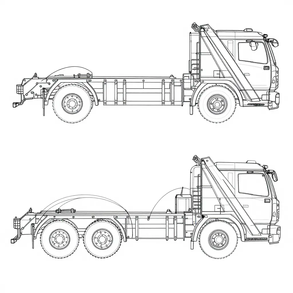
Front to rear: the paired horizontal lines are the chassis frame rails, the thin line above them is the tipper subframe, and the shaded gap between the two is where shims, pads and clamp torque are verified. The paired clamps at the front are the U-bolt pair, the mid-length brackets are the cross-member mounts, the circle at the rear is the hinge pivot, and the triangle under the body is the hydraulic cylinder base.
Pre-Delivery Mounting Checklist for Rough-Route Tippers
Walk this list with the workshop lead before the truck leaves the yard and write the readings down as you go. Our guide to subframe and lift cylinder checks explains where the torque values come from.
- Measure subframe-to-frame gap at every mounting point and log each reading.
- Record U-bolt torque point by point with a calibrated torque wrench.
- Check the grade marking on each U-bolt against the specification sheet.
- Measure pad compression at every mount for even, matched thickness.
- Compare cross-member spacing with the approved body mounting drawing.
- Inspect bracket weld toes for cracks, undercut and porosity under magnification.
- Confirm hydraulic cylinder base bolt torque, then re-strike the marks after settling.
- Torque body-to-subframe bolts in the sequence stated on the drawing.
- Re-check frame rail flange straightness near each bracket after final tightening.
- Photograph each mounting point and file the readings in the delivery pack.
Distributing Load: Cross-Members, Plates and Mounting Interfaces
Where the Load Actually Travels
Payload lands on the floor plate, spreads into the longitudinal body rails, drops through the cross-members into the subframe, and reaches the chassis rails and axles from there. On a rough route each pothole, kerb hop and speed hump turns that static load into a dynamic spike, so the mounting interface sees far more than the tare-plus-payload figure on paper. Where the load sits matters as much as how much of it there is: load placement can fill the axle long before it fills the body, which is why the rear mounting zone usually carries the heaviest work.
Cross-Member Spacing Sets the Flex
Collection bodies usually run 500-700 mm between cross-members, tightened near the hoist, tailgate and rear axle where reactions peak. Deflection rises faster than span does, roughly with the cube of the unsupported length for a concentrated load, so a 900 mm gap moves about three times as far as a 600 mm gap under the same load. On washboard lanes and broken shoulders that movement works the mounting bolts loose and pumps fatigue into every weld around them.
Reinforcement Plates and Bracket Ends
Reinforcement plates spread a bracket’s reaction over a wider patch of rail, and their thickness should follow the rail flange rather than the body floor. Squared-off bracket ends create an abrupt stiffness change that pulls stress into one narrow band; tapered ends and rounded corners last longer. Do not weld across the rail flange, and check plate thickness against axle rating and route severity when you choose the body steel grade and plate thickness.
Continuous Subframe vs Intermittent Mounting Blocks
| Criterion | Continuous Subframe | Intermittent Mounting Blocks |
|---|---|---|
| Load spread | Wide, low local stress | Concentrated at each block |
| Fatigue exposure | Lower peak, uniform cycles | Higher peak, block-edge cracking |
| Rough-route tolerance | Absorbs flex along its length | Blocks rock and work bolts loose |
| Corrosion risk | Traps moisture between rails | Better drainage and inspection |
| Repair cost | Longer cut-and-weld job | Individual block replacement |
A continuous subframe spreads reaction along the whole rail, which keeps local stress low and suits heavy compaction duty on poor roads. Intermittent blocks cost less to build and drain better, but they push the same load into a handful of small footprints, so each block sees a higher fatigue load. On rough collection work, count the blocks, measure the gaps and inspect for cracks at every plate end before signing off the build.
U-Bolt Clamp Load Retention by Mounting Position
Clamp load is what keeps a tipper body bolted to the chassis rails, and once the truck starts working rough routes it bleeds away at a different rate at each mounting point. The chart below illustrates that pattern.
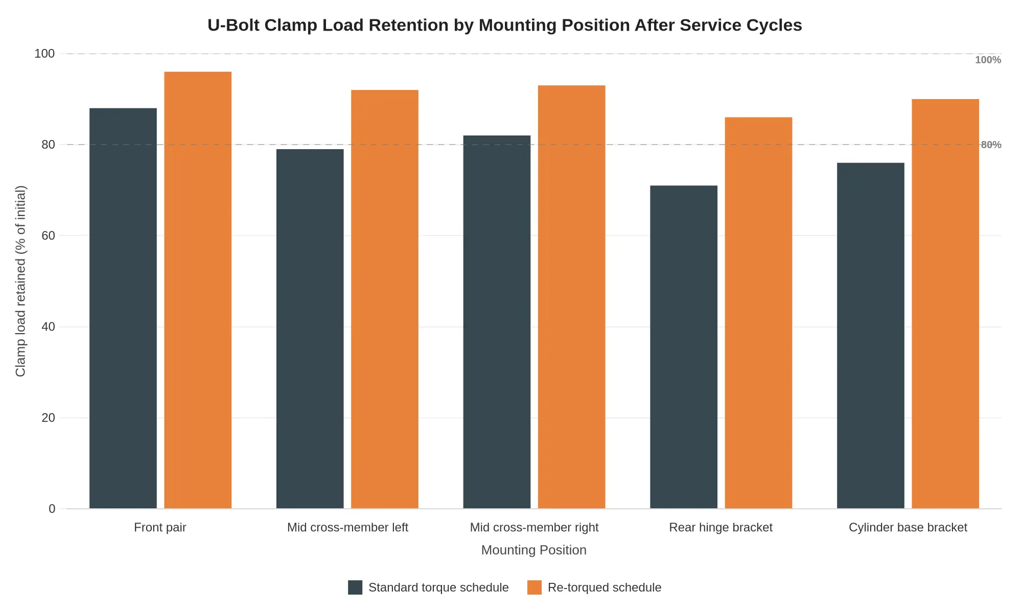
Illustrative figures, not a measured fleet survey: clamp load retention varies by mounting position, and a scheduled re-torque narrows the spread between positions.
What the Chart Tells You
- The rear hinge bracket and cylinder base bracket are the weakest points in the illustrative schedule, holding roughly 71% and 76% of initial clamp load.
- The front pair holds up best at around 88%, which is not a green light: it carries the largest share of weight transfer from the body.
- A re-torqued schedule lifts every position and closes the gap between them. The hinge bracket gains the most.
- Interval-based re-torque therefore beats one-time assembly torque on routes with potholes, wet refuse and repeated tipping cycles.
Frequently Asked Questions
How often should body-to-chassis mounting fasteners be re-torqued on rough collection routes?
At 500 km, then every 5,000 km or 30 days on rough routes. Inspect after any shift with heavy pothole or kerb impacts. Use Grade 8.8 or 10.9 hardware torqued to the builder’s specification and checked cold with a calibrated torque wrench.
Can mounting checks be performed without removing the tipper body?
Yes. Visual and torque checks run in place from the chassis rails and subframe, with the body lowered. U-bolts, mounting brackets and spring hanger fasteners stay accessible. Only cracked welds or elongated holes hidden above the subframe require lifting the body.
Does subframe design need to change for wet or corrosive waste streams?
Yes. Specify full-length subframe rails, continuous seam welds, and hot-dip galvanised or epoxy-coated steel of 6 mm or thicker. Add drain holes so leachate cannot pool between body and rails. Where stainless fasteners are used, fit isolating pads between stainless and carbon steel, because that pairing sets up a galvanic couple that corrodes the frame rather than the bolt.
What documents should a manufacturer provide to prove mounting checks were completed?
A signed pre-delivery inspection sheet listing every fastener location, torque value and wrench calibration date. Ask also for U-bolt and bracket torque records, weld inspection reports with NDT results where specified, and the chassis builder’s body-mounting approval letter keyed to your VIN.
Closing the Specification: Six Items to Lock Before Signing
All of it comes down to one build document. Before approving a garbage tipper truck for rough collection routes, write these six items into the purchase specification and treat any substitution as a change request in writing:
- Subframe geometry drawing: dimensioned and tied to your chassis wheelbase and frame-rail height, not a generic sketch reused across models.
- Fastener grade and torque schedule: grade, diameter, torque value and rigid-versus-spring mount type listed per mounting position.
- Pad material and thickness: elastomer hardness and thickness stated numerically, because soft pads flatten within one season of washboard lanes.
- Cross-member spacing: the actual spacing at the hopper, the compaction zone and the tail, not one averaged figure.
- Weld inspection record: the report with penetrant or ultrasonic results attached, rather than a certificate of conformity on its own.
- Re-torque interval: an interval in kilometres or operating hours, plus the torque values the workshop applies each time.
Mounting discipline, not body capacity, is what decides service life on rough routes. A modest body on a correctly drawn subframe outlasts a light body that hammers its fasteners loose. The difference shows up early at inspection, and body-to-chassis alignment also governs how cleanly the tailgate closes, which is the same root cause behind leachate drips and seal gaps. A manufacturer working under a strict quality system supplies all six records as standard documentation. One that cannot is telling you something useful.
Records Travel With the Truck
The delivery pack should hold the signed inspection sheet, the torque log with the wrench calibration date, pad thickness readings at every mount, the weld inspection reports and the subframe drawing revision that was actually built. Keep one copy in the cab file and one in the workshop file, because the first re-torque at 500 km is only meaningful against those numbers. Without them, the second inspection starts from nothing.