Garbage Tipper Truck: Why Wet Refuse Sticks in the Front Corner, and the Dump Angle That Clears It
On a tipping-body garbage truck, wet refuse sticks to the floor and headboard, then builds up in the front corner, cutting usable volume and ending the tip with someone inside the body and a scraper. The cause is mechanical rather than incidental: a high-moisture load bonds to steel, then resists the sliding motion the tipping cycle depends on. The body can look empty from the cab while a measurable mass still sits against the headboard.
The Five Terms That Define the Problem
A garbage tipper truck is a refuse collection vehicle built around a tipping body that discharges its load by gravity when the body is raised. Whether the body is a plain box, a compactor body or an ejector type, it sits on a subframe and is lifted by a hydraulic cylinder or a scissor arrangement rotating about a rear pivot. Discharge depends on the load sliding, not on being pushed, which is why material behaviour at the floor plate matters as much as hydraulic capacity.
Wet refuse adhesion is the tendency of high-moisture waste to bond to steel through surface tension, suction and the cohesive strength of the sludge layer at the interface. Food waste, market residue, leachate-soaked fines and wet fibre all form a paste that fills the micro-profile of the floor plate and acts as an adhesive film between load and body. Once that film forms, the load stops behaving as a free-sliding mass. The mechanism is the same one that cracks hopper floors under wet commercial bins on rear-end loaders.
Front corner retention is the concentration of adhered material in the corner formed by the body floor and the headboard. During tipping the front of the body rises, so this corner becomes the highest point of the floor, the furthest point from the discharge opening and the last place leachate drains from. Partial loads, compaction pressure and leachate pooling all collect there.
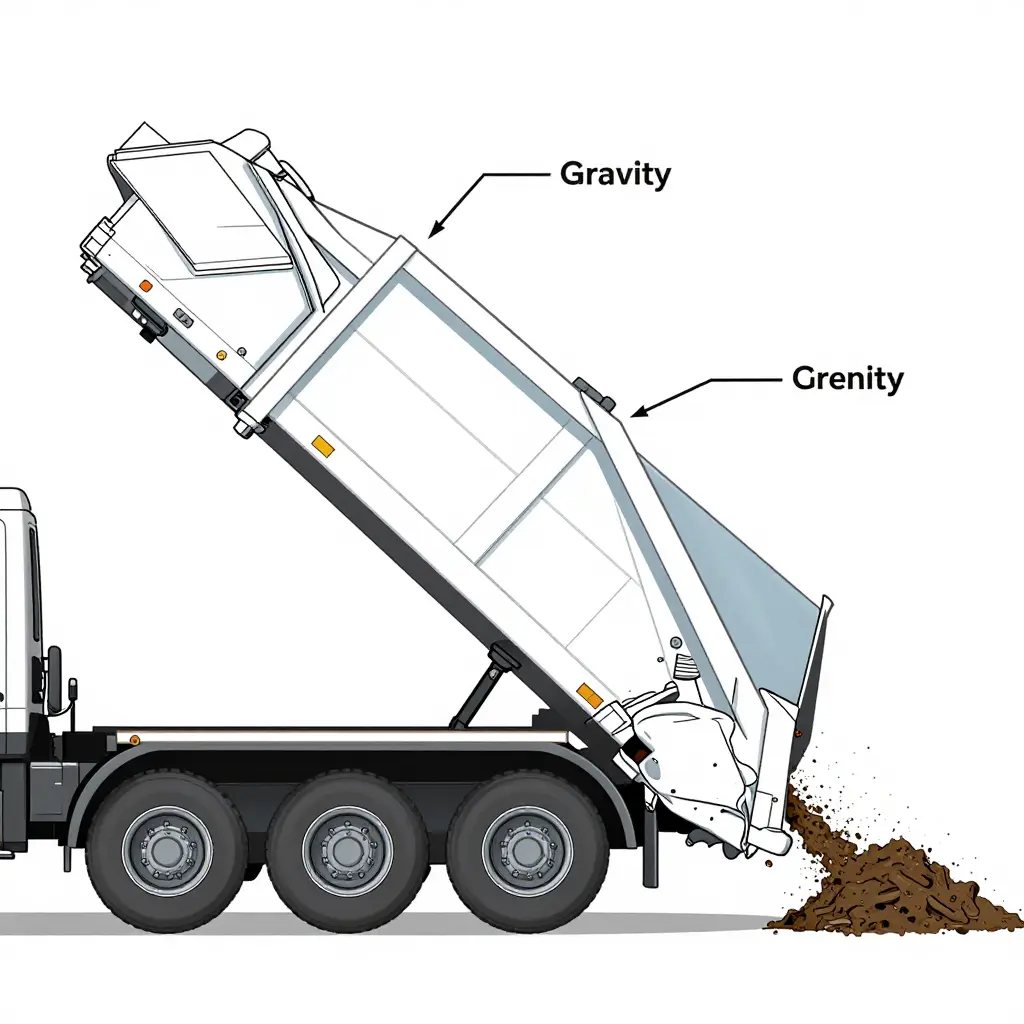
Dump angle is the angle of the body floor relative to horizontal at full raise, measured at the pivot. Geometry decides whether gravity can overcome friction and adhesion; no amount of pressure will compensate for a floor that never gets steep enough. Published figures are usually quoted at the floor rather than at the body sides, and the usable angle is often less than the nominal maximum because of cylinder stroke, hinge height and chassis clearance.
Residual load is the mass remaining in the body after the tipping cycle, in tonnes or as a percentage of the rated payload. It is the operational score for the whole system. Residual that stays much the same as the angle rises points to adhesion and geometry; residual that clears only at full raise points to insufficient angle.
What Decides Whether a Wet Load Clears
Front-corner sticking is the visible result when adhesion and geometry both go the wrong way at once. A wet load bonds to the floor through suction and a leachate film, friction at the plate and side walls adds to the resistance, and the body has to reach an angle that beats both before anything slides. Cylinder sizing, pump flow, pivot and hinge position, headboard shape and floor condition each put a ceiling on that angle. What a driver or workshop can measure matters more than any single factor: the angle reached at full stroke, the residual weight after a cycle, leachate drainage, floor and liner condition, and the pressures at the top of the stroke.
Why Wet Refuse Sticks in the Front Corner of the Body
A wet load rarely leaves a tipping body cleanly, and the usual evidence is a compacted wedge still sitting in the internal corner after the ram has finished. The sequence from condition to mechanism to symptom is predictable, and it ends in the same place every time.
Moisture content and matrix suction
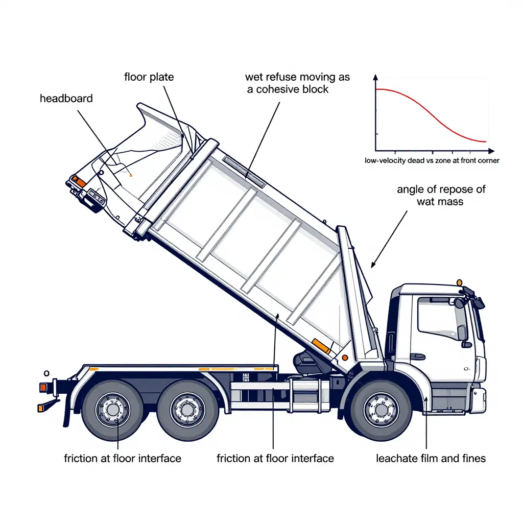
Water in wet refuse is not free liquid. It sits in thin films and capillary menisci bridging individual particles, and those menisci generate matrix suction, a negative pore pressure that pulls particles together and gives the load apparent cohesion it would not otherwise have. At the front corner the effect shows up as a mass that keeps its shape long after the floor has tilted past the point where dry waste would have slid clear.
Bulk density, saturation and angle of repose
Saturated refuse fills every void with water, so bulk density climbs and each cubic metre presses harder on the floor plate. Water also softens particle interlock, and the two effects pull in opposite directions: interlock falls, but suction adds cohesion, and in putrescible waste the cohesion usually wins. The result is a denser mass that holds a steeper face than dry refuse and spreads against the headboard instead of shearing and rolling rearward. What ends up packed into the corner is the wettest, densest, best-bonded fraction of the load.
Floor friction and surface roughness
Sliding only happens when the gravity component along the floor beats friction at the interface, and friction scales with normal load, which is highest where the load is deepest. Wet waste leaves fines and leachate that dry into a tacky film, raising the friction coefficient exactly where the load presses hardest. Corrosion and pitting make it worse, because a roughened plate gives the mass something to key into. How quickly that surface degrades is covered in our note on why the body floor rusts through first on rear-loaded compactor trucks.
Floor-to-headboard transition and its dead zone
The junction between floor and headboard forms an internal corner that sits outside the main sliding stream while the body tips. Flow velocity in that pocket drops to near zero, so shear stress on the waste falls below the threshold needed to move it. Load after load accumulates there, which makes the front corner the first area to pack out and the last to clear.
Load shift during transport and braking
Every brake application pushes the settled load forward, so the headboard carries the highest pre-compaction pressure before tipping even starts. That repeated forward shift squeezes the wet mass against a fixed wall and drives moisture toward the floor interface, strengthening the suction bond. By the time the body lifts, the material at the front is denser and better glued than anything behind it.
The mass moves as a block, not as a flow
With suction, friction and pre-compaction acting together, wet refuse leaves as one cohesive block rather than flowing like a granular material. A block moves only when the whole mass is mobilised, so a partial tip tilts it and lets it slump back into the corner. That is how a garbage tipper truck can appear to dump normally while the wedge stays put, and why a steeper angle or a deliberate shake cycle is often the only thing that breaks the bond.
| Condition | Mechanism | Symptom at the front corner |
|---|---|---|
| High moisture content | Capillary menisci create matrix suction and apparent cohesion | Mass holds its shape instead of breaking apart |
| Saturation of voids | Higher bulk density, added apparent cohesion | Dense mass that keeps a steep face and packs against the headboard |
| Wet fines and leachate film | Raised interface friction, keying into a rough plate | Load resists sliding even at a steep tilt |
| Floor-to-headboard geometry | Near-zero flow velocity in the internal corner | Dead zone where refuse adhesion builds up |
| Transport and braking | Forward load shift pre-compacts against the headboard | Densest, stickiest material ends up at the front |
| Combined effects | Cohesive block behaviour rather than granular flow | Clean rear discharge, retained wedge up front |
The front corner is where this chain ends, not a random collection point, and the way to empty it is to change the conditions that put material there.
The Front-Corner Retention Zone, Drawn Simply
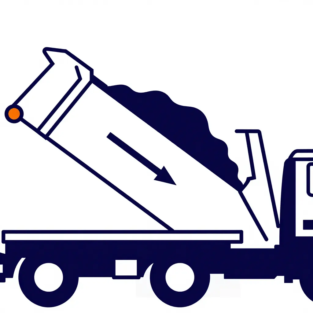
Figure 1. Side cross-section of a tipper body at a moderate dump angle. The single silhouette is the refuse mass; the arrow shows the sliding direction down the floor toward the tailgate opening; the orange marker sits on the front corner zone, where wet material is held against the headboard-to-floor junction instead of joining the flow.
Three references fix the geometry: the floor as a straight line, the headboard as the vertical wall at the raised end, and the tailgate opening as the gap at the low end. Tilt is read from the slope of the floor alone. Wheels, cab and chassis are left out because none of them changes where material lodges.
What the geometry shows
- The sliding vector runs parallel to the floor, so the driving force falls as the tilt decreases; gravity has less of a run to work with.
- The corner is a dead zone. The headboard stops horizontal movement and the floor stops vertical drop, so the mass has no free face to peel away from.
- Suction and cohesion scale with the contact area pressed into that corner, which is why wet, high-moisture loads release last exactly where the highlight sits.
- The tailgate gap sets the discharge throat. If the mass cannot rotate into it, raising the angle adds stress at the corner without adding flow.
When the material finally comes away it tends to move as a slab rather than a stream, and it lands hard on the plating behind the tailgate. That is one reason the surfaces that trap wet refuse are also the first to thin and corrode, as covered in our notes on why the body floor rusts through first. Compare the angle in the drawing with the angle the truck actually holds with a load aboard; the gap between the two is usually where the problem lives.
These design and operating conditions make front-corner retention worse, and on a working truck they usually appear together.
- Moisture and leachate – free liquid wets fines against the headboard, gluing wet refuse into the corner and destroying the slide film the load needs to move.
- High organic content – food, green and putrescible waste compacts under road vibration into a dense, sticky mass that grips the plate instead of shearing off it.
- Floor plate wear and pitting – scored and pitted decking raises friction and traps fines, so check the plate before spending money on the hoist.
- Headboard-to-floor weld geometry – square internal corners and proud weld beads form a pocket where material lodges and cannot be swept out.
- Insufficient body tilt – a low dump angle leaves the floor below the material’s slide threshold, so the load stalls instead of flowing.
- Partial-tip discharge practice – easing the body up part-way and lowering it lets material settle back and re-anchor in the front corner.
- Load left standing in the body – overnight or weekend dwell lets wet refuse dewater and set, hardening the residual into a crust that has to be dug out.
- Under-specified hydraulic tilt capability – marginal cylinder force and slow ramps force operators to tip at reduced angles, which caps the dump angle they can reach.
Because these conditions compound, a single worn floor, low tilt or missed clean-out rarely explains persistent front-corner sticking on its own.
Residual Material Retained vs. Tipper Body Dump Angle
The complaint is usually the same: “the load just won’t come out.” This chart is a quick way to test whether angle is the cause. It plots residual material left in the front corner after a full cycle against body tilt, using a wet, high-moisture commercial load as the example. The bars are an illustrative case, not a measured test series, and the useful information is in the shape of the curve rather than the individual percentages.
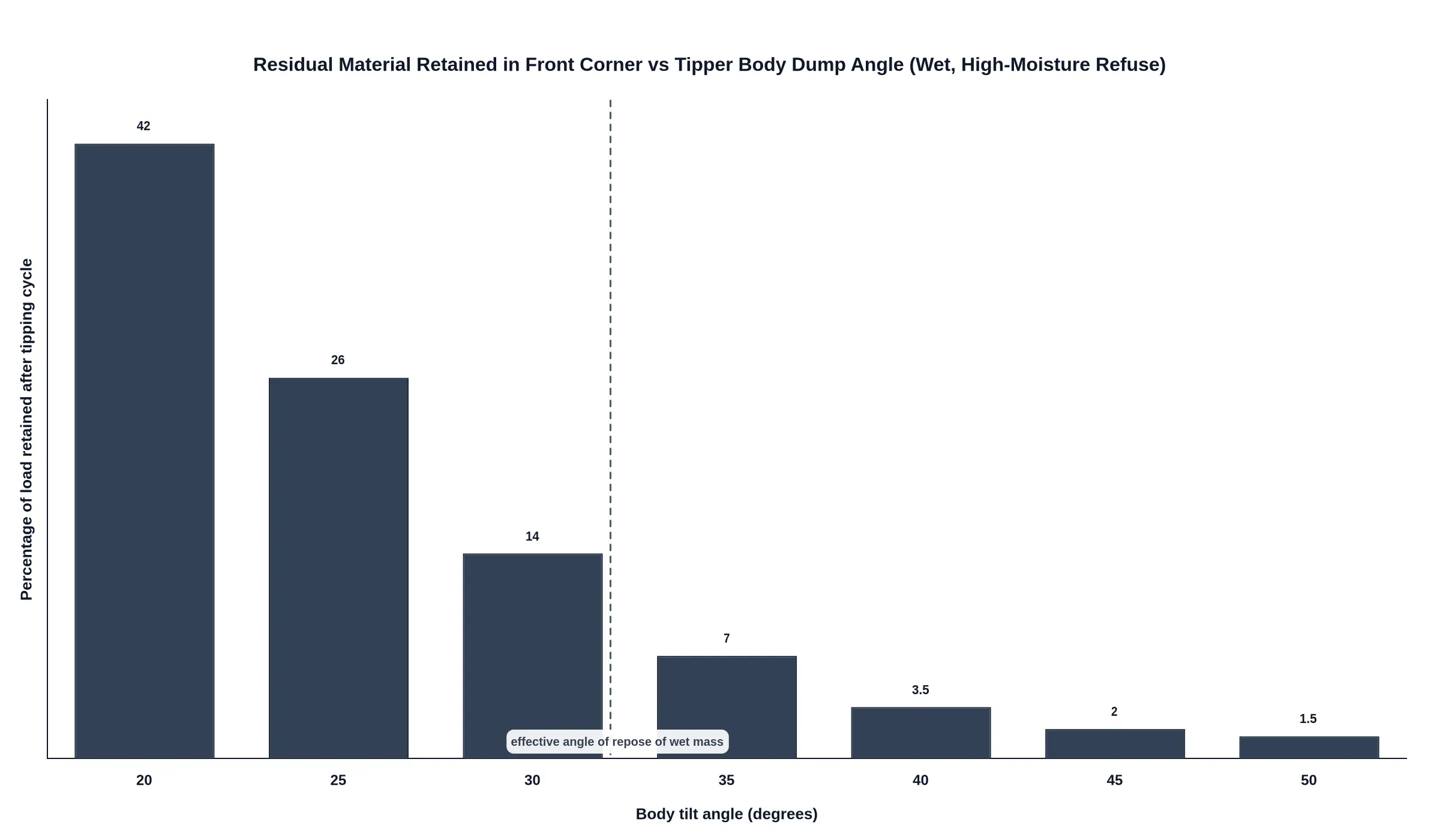
How to read it: each bar is the percentage of the load still sitting in the front corner at a given dump angle. The shape to watch is the steep drop in the 30-40 degree band and the flattening above 45 degrees.
Where the curve breaks
Wet municipal refuse behaves like a cohesive, high-friction paste rather than dry aggregate, so its effective angle of repose sits well above the 35-40 degrees typical of dry waste. The break in the curve comes when the tilt approaches that repose angle: for a moderately wet load, around 40 degrees. Saturated organic waste shifts the break higher, into the mid 40s and beyond.
- 20-25 degrees: the body is still acting like a container. Retention sits at 42 percent and 26 percent respectively, because the wet mass is simply being carried uphill.
- 30-40 degrees: the effective angle of repose is crossed. Retention falls from about 14 percent to 7 percent and then to 3.5 percent, halving with every few degrees of extra tilt.
- 40-50 degrees: diminishing returns. The last of the residue down to around 1.5 percent costs hydraulic pressure, cycle time and structural stress on the hoist, subframe and rear hinge while clearing very little.
Setting a realistic dump target
Use the band the load calls for, measured at the floor with an inclinometer rather than at the cylinder rod end: 50-52 degrees for moderately wet refuse, 55-58 for saturated organic waste. If body geometry or hoist limit cannot get there, a bigger pump is rarely the answer. Radiused front corners, UHMWPE or stainless liners and a vibratory or air-blast assist do more for a cohesive wet load than another 500 psi of line pressure.
Ignoring the curve costs more than a sluggish tip. Residual wet refuse against the floor keeps the steel permanently damp inside the corner weld, which is where pinholes start, and the trapped mass adds dead weight to every subsequent axle loading calculation. Fleets that track retention against tilt usually find a two-degree change in the tipping routine pays for itself faster than a hardware upgrade. Log the angle at which each body actually clears, and treat a rising trend as an early warning that the liner, headboard or floor is no longer slippery enough to shed the load.
The Dump Angle That Actually Clears Wet Refuse
Most sticking complaints turn out to be angle problems, and usually small ones. A garbage tipper truck that lifts to a nominal 48° and leaves a wet wedge in the front corner is tipping at the material’s limit, not failing to tip, and the last few tonnes simply refuse to slide. What follows is a sequence for finding the angle that works, not a case for a bigger pump.
Step 1: Measure the material behaviour, don’t assume it
The controlling number is the angle of repose of the wet refuse as it actually sits in the body: the steepest slope the material holds before it slides on itself. Saturated putrescible waste with high moisture, plastic film and food slurry typically sits far steeper than dry, high-cardboard loads, often in the high 40s to mid 50s, though any published range is a starting point that should be confirmed on your own route.
A practical field method: tip a sample of the load onto a clean concrete slab, let it stand, and measure the slope. Then repeat against a sample of the body floor plate, because steel-to-refuse friction is not refuse-to-refuse friction. Wet loads also behave differently at rest than in motion: adhesion and suction at the floor surface raise the effective resistance above the static repose value, and that gap is what leaves the front corner loaded.
Step 2: Set the target angle with a margin above repose
An angle equal to the angle of repose is by definition the angle at which the material is on the verge of sliding, not sliding. A body tilt that matches repose produces stall, spring-back and a residual wedge, because three resistances sit on top of the repose angle:
- Floor adhesion from leachate and fines acting as a weak glue.
- Side-wall and corner friction, highest at the front bulkhead where material is deepest.
- Load bridging, where a stiff mass spans the body and carries itself instead of flowing.
A working margin of roughly 5-10° above the measured repose is the usual starting point, applied as the held angle at the top of the stroke rather than the peak reached momentarily. Packed density matters too: denser loads need more angle than loose ones to break the same bond, which is why it is worth understanding how compaction ratio sets what the body actually carries before fixing the geometry. The front-floor region sees the steepest required slope, so a design that only just clears at the tailgate will still hold material forward.
Step 3: Check tailgate opening height and the floor-to-tailgate transition
No dump angle clears a body if the discharge aperture is the bottleneck. Three things govern it:
| Check | What to look for |
|---|---|
| Tailgate opening height | Opening comfortably larger than the biggest expected lumps and the deepest likely slug of material; a low opening throttles flow and backs material up the floor |
| Floor-to-tailgate transition | Flush, ramped and free of a raised lip, hinge barrel or weld bead that acts as a dam |
| Side-wall taper | Slight outward flare at the rear reduces corner hang-up |
A surprising amount of wet refuse parks at the floor-to-tailgate junction. A 20-30 mm lip is enough to hold back a slurry wedge that then never gets pushed out, however high the body goes.
Step 4: Confirm the hydraulics can achieve and hold the angle
Two discharge strategies behave very differently:
- Full-tip cycle: one continuous lift to the target angle, hold, then lower. Best for wet refuse, because the material keeps moving and never gets a chance to re-settle and re-bond.
- Staged or vibrated discharge: raising in increments, or shaking the body with the hoist. Staging can release a bridged load, but each pause lets the mass consolidate, so a staged cycle often needs a higher final angle than a full tip. Vibration is a recovery tool, not a substitute for angle.
Either way, check cylinder geometry, relief-valve setting, pump flow, PTO speed and oil temperature at the top of the stroke. Many bodies reach the target angle cold and then creep back under load, which reads to the operator as material sticking when it is really pressure bleed. Confirm the body holds the target angle for a full minute with the load aboard.
Step 5: Verify by residual load, then iterate
After a cycle, walk the body with the hoist still up and note where material remains:
- Even film across the floor – angle is close but marginal; add a few degrees.
- Wedge in the front corners only – the limiting factor is the front-floor slope or corner geometry, not total tilt.
- Band along the side walls – wall friction or a non-flared body; consider liners before more angle.
- Material heaped against the tailgate – aperture or transition problem, not angle.
Record residuals per route type over several cycles before changing anything. One observation tells you where it sticks; a pattern tells you why.
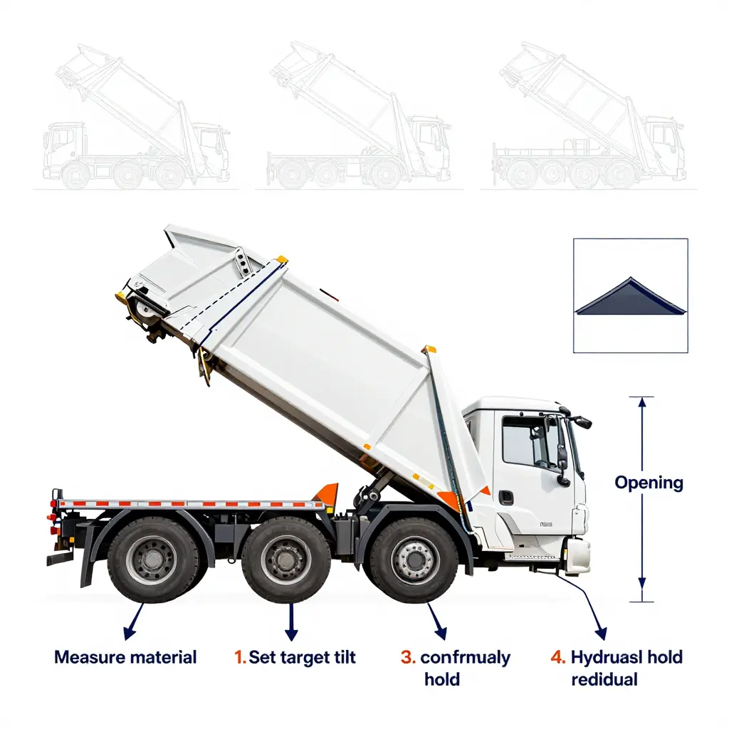
Measure the material, set the target with a margin above repose, prove the hydraulics hold that angle under load, then read the residual and change one variable at a time. Wet refuse is a geometry and discipline problem long before it is a hydraulic one.
Dump-Angle Reference Guide: Refuse Condition vs Body Specification
The angle that clears a load depends less on nominal body volume than on how the refuse behaves at the front corner. The table gives engineering reference ranges for the moisture conditions crews meet most often, including wet refuse that has already compacted in transit.
| Refuse condition | Typical moisture behaviour | Effective angle of repose range (deg) | Minimum recommended body tilt angle (deg) | Hydraulic and structural notes | Verification method to confirm load cleared |
|---|---|---|---|---|---|
| Dry mixed municipal waste | Free-draining, low cohesion, minimal floor adhesion | 35 – 40 | 45 – 48 | Two-stage cylinder reaching 48 deg; standard floor plate; tailgate clearance 20 – 30 mm sufficient | Visual check of front third of floor and both front corners after a 3 s hold at full tilt |
| Moderately wet waste | Some free liquid, partial cohesion, slides in a single mass | 40 – 45 | 50 – 52 | Cylinder stroke must reach 52 deg with margin; check subframe rail for torsion under offset loads | Hold at full tilt 5 s, confirm no ridge above roughly 100 mm at the front corner |
| High-moisture organic waste | Saturated, high adhesion, tends to smear and bridge | 45 – 52 | 55 – 58 | Long-stroke telescopic or dual-stage cylinder; full-depth subframe; tailgate clearance 60 mm or more | Raise, hold, lower part way and re-raise to release bridged material, then re-inspect corners |
| Compacted wet refuse with leachate | Liquid migrates to floor, load packs hard, corner pockets form | 48 – 55 | 58 – 62 | Front-end telescopic cylinder sized for full pressure at 62 deg; heavier subframe section; leachate drain and tailgate seal clearance checked | Watch tailgate and corner pockets during tipping; confirm free leachate flow and no residual foot of material |
| Bulky wet cardboard and packaging | Absorbs water, high friction, springs back when released | 42 – 50 | 52 – 56 | Stroke to 56 deg plus 2 s dwell; consider internal baffle and smoother floor finish | Dump twice at full angle and check for packaging trapped behind the front corner radius |
| Frozen or slush-mixed refuse (winter routes) | Ice bonding, low initial flow, sudden release once broken | 40 – 50 | 55 – 60 | Cylinder must hold 60 deg without settling; cold-weather hose and seal rating; subframe check for frost damage | Confirm release of the whole block in one pass, not in stages, before moving off |
These figures are engineering reference ranges rather than measured test data. Final dump angle, cylinder stroke, subframe arrangement and tailgate clearance have to be confirmed against the specific body geometry and hydraulic specification before a written operating procedure is issued.
Use the highest row that matches your load rather than averaging between rows, because wet refuse held at the front corner keeps the rest of the body loaded even when the bulk has already slid. Fleets running mixed routes should log which rows their vehicles actually reach: the same body needs a noticeably steeper angle once seasonal moisture rises or when loads sit overnight. The moisture behaviour also shows up earlier in the cycle, where wet refuse is loaded rather than tipped, as these notes on wet loading conditions on rear-loader bodies explain.
What Limits the Dump Angle: Cylinder Stroke, Subframe and Body Geometry
A garbage tipper truck that leaves a wedge jammed in the front corner is usually not badly designed; it was specified around a different load. The load needs one dump angle, the hardware delivers another, and the shortfall can be measured rather than guessed at. A driver’s report that “it won’t tip clean” usually describes exactly that gap.
What the load needs
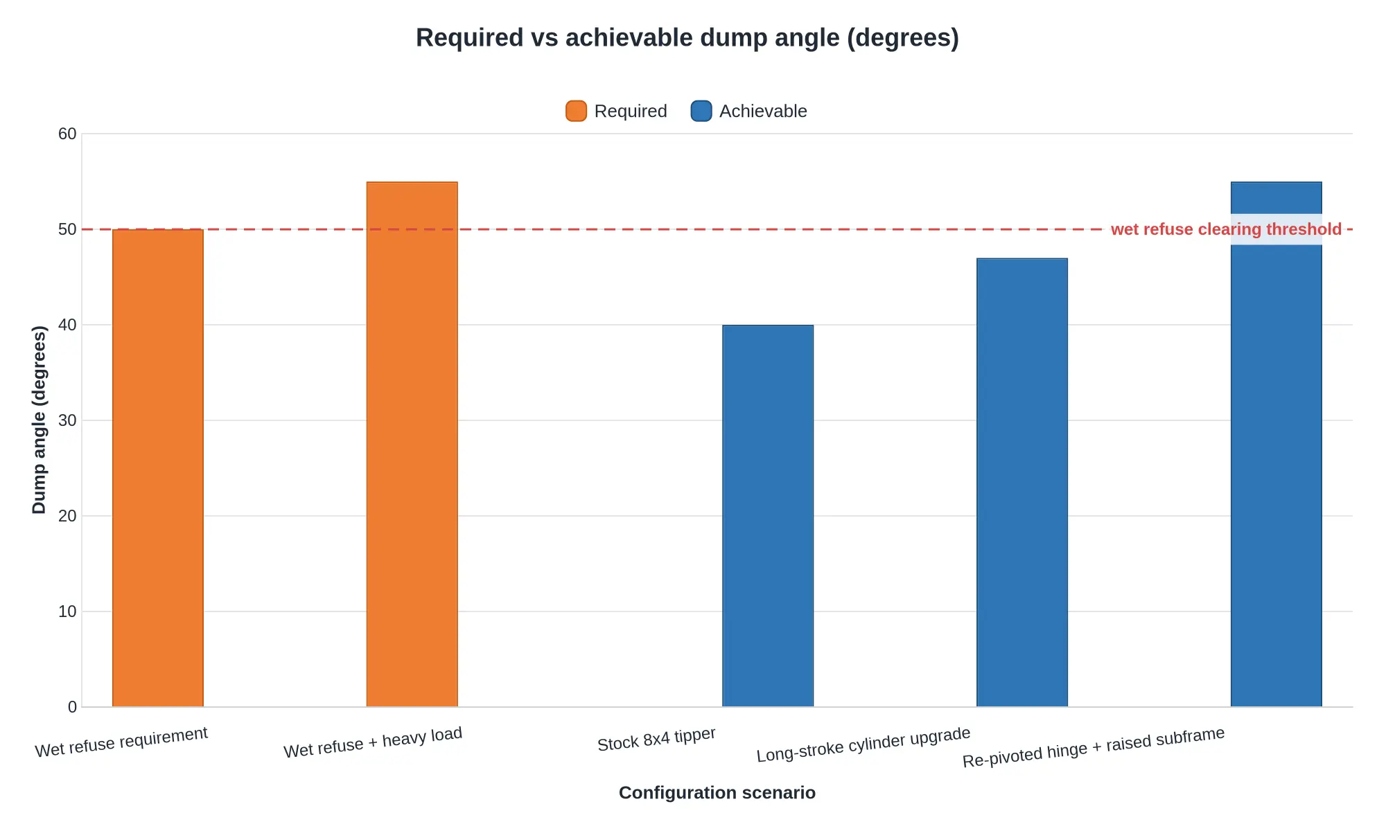
Dry municipal waste with a loose, granular structure holds a repose angle of roughly 35-40° and flows out once the body passes about 45°. Wet, leachate-bound refuse – food waste, market waste, rain-soaked commercial bins – behaves like a cohesive paste with an angle of repose of 45-55°. Below that threshold the load shears and clings rather than sliding, and the front corner becomes the pivot point for a stuck plug. A working specification is therefore 50° minimum, with 55° or more on heavy wet loads.
Where the angle is lost in the hardware
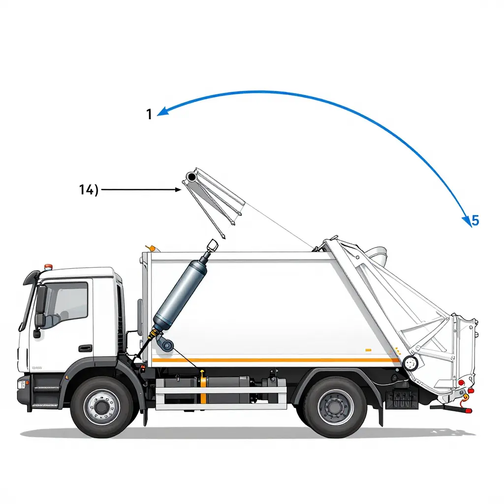
Hydraulic lift cylinder stroke and mounting geometry
Final angle is set by geometry, not pump pressure. Usable angle depends on the hydraulic lift cylinder stroke and the sine of the angle between ram axis and body, measured from the mounting points, so two trucks with identical rams can reach different angles because one has its base pin further forward or its trunnion mounted lower. The effective lever arm also shortens as the body rises, which is why the last 10° of lift is the slowest and the most pressure-hungry.
Tipper subframe and hinge pivot position
The tipper subframe carries the hinge, and the pivot’s height above the chassis rail together with its distance from the body’s rear face determines how much stroke converts into rotation. A low, forward-set pivot caps the angle no matter how large the cylinder is. Pivot brackets are also a classic fatigue point, so verify the hardware is healthy before condemning the geometry; these subframe and lift cylinder inspection checks cover the wear patterns that quietly steal effective stroke.
Chassis frame clearance
Clearance is the invisible limit. Crossmembers hitting the rails, a prop or tailgate fouling the rear overhang, mudguards contacting the body or a tailgate lip grounding out all stop the lift before the ram bottoms out. If the body reaches 44° and stops with the ram still extending, the hydraulics are fine and something is touching.
PTO, pump output, relief valve and oil temperature
Flow rate sets speed and pressure sets force. A PTO-driven pump delivering modest litres per minute lifts an empty body briskly and crawls under a wet, dense load, because flow and load weight interact through pressure. The relief valve caps maximum pressure, and therefore the maximum liftable moment, which usually shows up as a stall in the steep final third of the stroke. Oil temperature compounds both: cold oil is viscous, flow drops, lift slows, the relief valve chatters and the body can hang mid-tip. The behaviour is documented in these notes on cold-start hydraulic stalls and is worth ruling out before anything is re-engineered.
The size of the gap
Typical modern tipper bodies reach 42-48° of geometric maximum. Against a 50-55° demand from wet refuse, that is a real shortfall, not an operator error.
| Constraint | Symptom on site | Typical shortfall | Realistic remedy |
|---|---|---|---|
| Cylinder stroke / mounting | Ram fully extended, body short of target | 5-10° | Longer stroke ram, repositioned base pin |
| Hinge pivot geometry | Angle caps regardless of load | 5-8° | Re-pivot hinge, raise pivot height |
| Chassis clearance | Body stops with ram still moving | 3-6° | Relocate crossmembers, trim fouling points |
| PTO pump flow | Slow lift, stalls under wet load | Speed, not angle | Higher-flow pump, larger lines |
| Relief valve setting | Stall in final third of stroke | 0-8° | Verify setting against rated pressure |
| Cold oil viscosity | Morning stalls, jerky hold | Speed and hold | Correct oil grade, warm-up cycle |
Structural consequences of over-tilting
Raising the angle on a chassis that is not rated for it is the expensive mistake. Tilting further moves the centre of gravity rearward and increases the moment on the hinge brackets and rear frame rails, which are designed for a defined torsional envelope rather than an open-ended one. Over-tilting shows up as torn hinge gussets, cracked rail flanges behind the rear spring hanger, subframe web cracks, and a PTO shaft or prop running at an angle it was never balanced for. It also erodes the stability margin on soft or cross-sloped ground, where a body at 55° on a chassis rated for 45° has very little left in reserve.
Closing the gap, cheapest fix first
Work outward from the least invasive change: confirm the relief valve setting and oil condition, check pump flow against load weight, look at clearance and fouling, and only then consider stroke and pivot geometry. Geometry work is the only fix that buys permanent angle, but it also demands a structural sign-off on the subframe and frame rails. Specify the target angle, the load density it must clear and the rated envelope of the chassis in the same conversation, and the trade-off becomes explicit.
The Geometry Behind Every Dump Angle
The mechanism reduces to a triangle of forces and distances. The chassis frame is the fixed reference, the body floor is a line rotating about the rear hinge pivot, and the lift cylinder is the link whose extension drives that rotation. The angle between chassis and floor is what a wet load actually experiences.
Because the cylinder acts along a chord while the body rotates about a fixed point, stroke and angle are never linearly related. The same 100 mm of rod extension buys a large slice of angle at the start of the lift and progressively less near the top. That is how a partially stroked cylinder can look healthy while leaving the body short of the angle needed to release sticky refuse from the front corner.

Figure: Chassis frame as horizontal reference, body floor as the rotated line, hinge pivot, cylinder chord, and the resulting tilt angle arc.
Mounting geometry sets the ceiling on achievable angle: if the cylinder’s lower mount is too far forward or the upper mount too low on the body, no amount of pressure reaches a clean-shedding angle. Anything that shortens effective stroke – a bent rod, worn pins, air in the circuit, a relief valve set low – shows up as an angle shortfall long before it shows up as a visible leak. Checking rod travel against the arc, rather than judging the lift by eye, separates a hydraulic fault from a wet-load handling problem. The inspection routine that pairs with this geometry check is set out in our notes on subframe and lift cylinder checks.
Operational Checks That Keep the Front Corner Clear
A garbage tipper truck clears its load only when tilt geometry and floor finish both hold to standard, so these checks belong on the daily walk-around and the service schedule.
- Confirm full tilt is reached and held before the tailgate latch is fully released; let the body settle at maximum angle for a few seconds, then open the gate.
- Watch the last degrees of travel for hesitation, stall or a throttle-assisted finish that suggests a short dump angle.
- Inspect floor plate flatness at the headboard junction with a straightedge; record dishing, waves and raised weld beads that shelter material.
- Examine weld seams along that junction for undercut, toe cracks and corrosion lifting the bead.
- Probe for pitting and surface roughness across the forward third of the floor, and log pit depth and coverage.
- Compare lift cylinder stroke and hydraulic pressure against specification at operating temperature, front and rear stages.
- Check tailgate hinge pins, bushings and seal lip for play and gaps that let material ride back into the body.
- Measure body-to-chassis pivot and bracket wear, then confirm the effective angle still matches the geometry chart.
- Specify floor plate thickness and surface treatment – grade, hardness, coating, weld finish – in writing at the next body purchase or rebuild.
Every check guards the same threshold: the moment gravity has to beat adhesion. Once the dump angle slips a few degrees short, through pivot wear, a soft cylinder or an operator releasing the gate early, wet refuse stops sliding and starts packing into the front corner as residual load that shaking will not release. Floor condition is the other half of the equation, because pits and rough weld beads give wet refuse something to grip. Plate thickness and finish therefore belong in the specification, with the floor plate thickness and treatment to specify next time as a worked example. Logging all nine items on one sheet also shows whether a clearing problem is hydraulic, structural or simply a worn floor.
FAQ: Wet Refuse Sticking and Dump Angle
Why does wet refuse stick to the front corner of a garbage tipper truck body rather than sliding out?
In a garbage tipper truck, wet refuse sticks because moisture forms a suction film between the load and the steel floor, and the front corner gives that film the fewest escape routes. As the body tilts, material at the headboard has the longest distance to travel to the discharge opening, drains last and carries the most pre-compaction pressure. Cohesive, high-moisture waste compresses into the corner instead of shearing free.
What dump angle is generally needed to release wet or high-moisture refuse?
A dump angle of roughly 45-50 degrees above horizontal clears dry refuse. Moderately wet loads need 50-52 degrees, saturated organic waste 55-58, and compacted refuse carrying leachate more again. Moisture raises both internal friction and cohesion, so a load that leaves a smooth body at 42 degrees may need a steeper tip plus vibration or a push-plate assist to release completely.
Can a higher tilt angle alone solve front-corner retention?
No. Raising the dump angle helps bulk release, but it cannot free material that has already adhered and lost contact with the main mass. Front corner retention is typically a geometry and surface problem: square internal corners, floor-to-sidewall welds, and a dry, scuffed or lightly rusted floor hold wet refuse regardless of how far the body tips.
Does a lining or floor surface treatment reduce refuse adhesion?
Yes, but modestly. Smooth liners such as UHMW-PE or stainless sheet reduce friction and adhesion and speed discharge, yet they do not correct square corners or a floor that has become dimpled and rough. Surface condition matters more than the material name: an intact, polished liner outperforms a worn or contaminated one, so weld prep and cleaning schedules are part of the fix.
How can an operator tell whether the truck or the material is responsible for the residual load?
Compare residual load against a known baseline. If the body is overloaded or the payload is concentrated toward the headboard, weight and compaction pressure hold the residue rather than friction, because over-loading raises the normal force at the front corner. Then compare like with like: a clean, dry body that clears similar material points to the material, while one that retains everything points to geometry or surface condition.
Matching Body Specification to the Waste Stream
Wet refuse binds against the floor and headboard and flows poorly, so it does not release as a coherent mass when the body tips. Poor flow leaves residual material in the front corner, where floor, sidewall and headboard meet and gravity gives the load nowhere to travel. Whether that material clears depends on two variables acting together: the body tilt achieved at full stroke, and the ability of the lift cylinder to deliver and hold that angle under a loaded, sticky mass.
Fleet managers and body manufacturers can work from that sequence directly. Specify dump angle, floor geometry and lift cylinder capability against the actual moisture profile of the waste stream, rather than defaulting to a standard tipper configuration carried over from dry-load practice. A route collecting wet commercial and putrescible waste needs a different specification baseline from one working dry debris, and where floor plate thickness and hopper geometry are already under review for wet loads (see this analysis), the same moisture data should set the tipped angle and cylinder sizing.
CRRC’s special vehicle production capability, quality system and product range, including garbage trucks and sanitation vehicles, support specification-based body selection.