Tipper Hydraulic Duty Cycles: Where the Heat Comes From
A tipper body on a garbage truck runs the same oil through the same path on every lift. The pump draws oil from the reservoir, the control valve routes it, and the lift cylinder raises the body. Each lift leaves some heat behind in that oil, and over a shift the oil has nowhere to shed it.
Hot oil is thin oil. Thinner oil slips past the clearances in the pump, valve and lift cylinder instead of building pressure, so internal leakage rises and less of the pump output reaches the ram. The driver notices it as a body that comes up quickly on the first few stops and labours by the afternoon.
A larger tank holds more oil, so the same heat load produces a smaller temperature rise. It also exposes more wetted wall area and gives the oil longer in the tank before the pump draws it again. An undersized tank runs hot early in the shift and stays hot.
Oil temperature, lift speed and reservoir size move together, and changing one in isolation usually leaves the other two where they were. A slow lift is also easy to misread, so it is worth comparing it against other tipper body lift issues before ordering parts.
Hydraulic reservoir size versus tipper duty cycle
Size the tank against pump flow and cycle rate rather than body volume: a 60 L reservoir fed by a 60 L/min pump will overheat inside an hour of steady lifting. The table below pairs nominal capacity with hourly cycle counts and the cooling each duty needs. The 60 L and 90 L rows assume a cooler is fitted, which is what keeps them working at those ratios.
| Nominal reservoir capacity (L) | Usable oil after expansion allowance (L) | Pump flow at rated speed (L/min) | Sustainable lift cycles per hour | Cooling requirement | Typical application |
|---|---|---|---|---|---|
| 60 | 48 | 40 | 8 | Air-cooled oil cooler required above 25 C ambient | 3-4 m3 tipper body, single-shift inner-city collection, 25 lifts per shift |
| 90 | 72 | 50 | 12 | Oil cooler recommended for shifts over 4 hours | 6 m3 tipper body, 40 lifts per shift, 2 stops per street |
| 120 | 96 | 60 | 16 | Cooler optional if oil stays below 70 C | 8 m3 tipper body, 60 lifts per shift, mixed commercial route |
| 160 | 128 | 70 | 20 | No cooler needed at 20-25 C, monitor sump temperature | 12 m3 tipper body, 80 lifts per shift, transfer station work |
| 200 | 160 | 80 | 24 | No cooler needed, reservoir surface handles heat rejection | 16-20 m3 tipper body, 100 lifts per shift, double-shift landfill runs |
Why Hydraulic Oil Heats Up Across a Shift
The heat in a tipper circuit is made where the oil is restricted. Every pressure drop across a valve, fitting or orifice turns pressure energy into heat, and that heat stays in the oil. On a garbage truck the restrictions are everywhere: directional spool lands, load-holding checks, pilot lines, hose elbows, and the metering edges that throttle the body down. A relief valve that cracks open when a load stalls turns the full pump output into heat while lifting nothing at all.
The duty cycle then removes the recovery time. Stop after stop, the lift cylinder makes full strokes with only a few seconds between them. Oil comes back to the tank hot and is drawn straight into the pump again, so the reservoir never gets the idle period it needs to shed heat. The tank is the main heat sink in the circuit, and a tank sized for occasional dumping but asked to run a collection route will keep climbing from the first hour to the last.
Where the heat gets in: the tipper circuit end to end
Oil leaves the reservoir, the pump pushes it through the directional control valve, and it does its work in the lift cylinder. What returns is not the oil that left: every restriction and every pressure drop along the way has added energy, which shows up as heat on the return leg.

Those four steps are the whole circuit: the pump supplies flow, the valve adds restriction, the cylinder applies the load, and the return line carries the heat back to the tank. The reservoir is where that heat is shed, through wall area and de-aeration. Too little volume, or a return line that dumps hot oil straight at the suction, and the next lift starts on oil that is already warm.
If the body is already lifting slowly and running hot, the same circuit is worth comparing against the symptoms in our notes on tipper body lift issues.
Slow Lifts: Why the Tipper Slows Down and How to Trace It
Owners often replace a pump on a hunch and get the same sluggish ram back. The lift circuit is a chain of flow: what the pump delivers, what the valve passes, what the cylinder consumes, and what leaks past the seals. Test that chain in order and the culprit usually shows up in an afternoon.
Pump displacement and drive speed come first
Flow is displacement multiplied by shaft speed, so a slow lift can come from a low PTO ratio, low engine rpm, or a pump that no longer moves its rated volume at pressure. Confirm the pump’s displacement against rated flow at the rpm you actually run, and check that the PTO and pump were specified together for this duty cycle – our notes on pump and PTO specification for batch compactor builds walk through the matching exercise. A pump running below rated flow is not a wear problem yet; it may be a specification problem.
Relief valve setting versus actual load pressure
Set pressure should sit above the peak pressure the load demands, with a sensible margin. If measured load pressure creeps within a few bar of the relief setting, the valve dumps flow over the top, and the lift gets slow and hot. A tired relief spring opens early, which looks exactly like a weak pump. Tee in a gauge, lift a full bin, and record the peak.
Lift cylinder bore and rod-side flow
A bigger bore holds more oil per millimetre of stroke, so the same pump takes longer to fill it. On double-acting rams the rod reduces the effective area on the retract side, so flow demand differs between directions. That geometry is fixed; wear is not. Piston seals that bypass rob flow quietly, and the ram gets slower as the oil thins. If bins stall part-way rather than simply crawl, the cause is usually elsewhere – see mid-stroke stalls on cart tippers.
Hydraulic oil temperature and viscosity
Viscosity governs how easily the pump draws and holds oil. Cold oil is thick, so morning lifts are slow by nature; hot oil is thin, so it slips past clearances and internal leakage climbs. A lift that is fine at start-up and slow after two hours therefore points to wear, not to a setting. Track oil temperature through a shift and compare it with the temperature the lift time was quoted at.
Spool and seal wear that bypasses flow
Worn valve spools, scored bores and hardened O-rings leak internally. The oil never reaches the cylinder, so nothing external looks wrong: no leaks on the ground, no visible damage, just a slow lift. Pressure testing at the cylinder port separates valve leakage from cylinder leakage in minutes.
Quote lift times against a baseline
A lift time means nothing without conditions. Quote lift times at rated pump flow, a defined oil temperature and a stated load, then measure every future test against that baseline.
| What changed against baseline | What it points to | First check |
|---|---|---|
| All functions slow, cold and hot | Pump flow, PTO ratio, engine rpm | Pump output at rated speed |
| Only the lift is slow | Cylinder bore, spool, ram seals | Pressure at cylinder port |
| Fine cold, slow once hot | Viscosity, internal leakage, seal wear | Oil temperature and pressure drop |
| Slow and hot, relief noisy | Relief set too close to load pressure | Peak load pressure vs setting |
A 10-second drift on a 40-second lift is worth investigating; a 15-second drift usually costs a route. Write the numbers down, and the next slow lift starts from a known baseline instead of a guess.
Lift cycle time versus hydraulic oil temperature
The chart plots full-raise cycle time against oil temperature for the same tipper body. Both curves climb, and the worn curve climbs faster, which is why a tired pump and valve feel “fine” on a cool morning and useless by mid-afternoon. If the numbers look familiar, our guide to tipper garbage truck body lift issues walks through the usual suspects in order of cost.
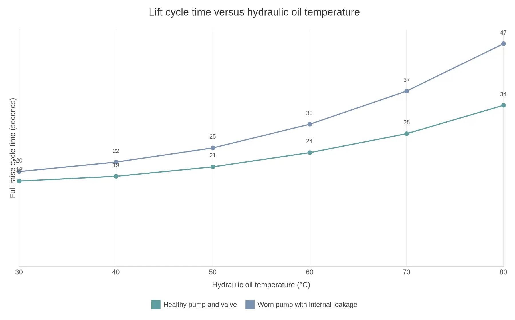
Every 10 °C of oil temperature adds roughly two seconds to the healthy truck’s full raise. The worn unit goes from 20 seconds to 47 over the same temperature range – more than double – because heat exposes the internal leakage that cold oil was hiding.
Specification checklist before ordering a tipper garbage truck
Hand this list to your supplier, and ask them to confirm each point in writing on the quotation.
- State the nominal and usable hydraulic tank capacity in litres. (Nominal tank volume versus usable oil volume above the suction point at maximum body tilt.)
- Fix a minimum reservoir-to-pump-flow ratio in the contract. (Reservoir litres divided by pump flow in L/min, for example at least 2:1 for a body that lifts repeatedly through a shift.)
- Specify an oil cooler or heat exchanger sized for continuous tipping. (Cooler type, rated heat rejection in kW, and the oil temperature rise it must hold at your ambient conditions.)
- Quote pump displacement at rated PTO speed, not at engine idle. (Pump displacement in cc/rev at the actual PTO ratio and engine rpm, plus resulting flow in L/min.)
- Set the relief valve against the maximum lift load, including a wet or stuck load. (Relief setting in bar, calculated from cylinder area and the heaviest body-plus-refuse load.)
- Define lift cylinder bore and stroke to suit the body geometry. (Bore x stroke in mm, rod diameter, mounting centres, and the maximum tipping angle reached.)
- Demand a guaranteed full-raise cycle time at a stated oil temperature. (Seconds from rest to full tip at a defined oil temperature and rated PTO speed, with the test load stated.)
- Require an oil temperature gauge and return filtration as standard. (Gauge range and mounting position, filter micron rating, bypass setting, and recommended service interval.)
- Agree a duty-cycle target in writing before the build starts. (Lifts per shift, operating hours per day, and the share of time the pump runs at full pressure.)
If you are comparing several quotes, read this garbage tipper truck sizing guide before you lock the hydraulic specification.
Tank Size Is a Scheduling Decision
A hydraulic tank size is not chosen to look balanced on the chassis. It sets how many lifts a tipper on garbage trucks can complete before the oil gets hot enough to slow the cycle. Every lift pushes pressurized oil through the pump, valves and cylinder, and part of that energy never reaches the load; it becomes heat in the oil. That heat can only leave through the reservoir walls, the return lines, the cylinder barrel and any cooler in the circuit. Heat going in depends on pressure and on the volume of oil moved. Heat coming out depends on surface area and on how long the oil sits between lifts, which is your duty cycle.
Reservoir volume therefore decides how much of the route runs on cool oil. A bigger tank raises the same heat input to a lower temperature and exposes more wetted wall area to reject it between lifts. Keep the oil inside its viscosity band and the pump holds volumetric efficiency, the relief valve stays shut, and lift speed at hour six matches lift speed at hour one. Run the tank too small and the oil thins, internal leakage rises, and each lift takes longer than the one before.
A practical sizing direction
| Duty pattern | Reservoir volume vs pump flow |
|---|---|
| Intermittent, light loads | 1.5 to 2 L per L/min |
| Standard municipal collection route | 2 to 3 L per L/min |
| Continuous high-cycle work | 3 to 4 L per L/min, plus an oil cooler |
So a truck running a 60 L/min pump on a normal route wants roughly 120 to 180 L of usable reservoir volume. The trade-off runs the other way too: oil weighs about 0.87 kg per litre, and a deeper tank eats frame-rail space and mounting height. Every extra 40 L is about 35 kg of tare weight that comes straight off payload, and it has to fit without fouling the body subframe. This is the same volume-versus-payload argument that runs through our manufacturer sizing guide and the body steel and hydraulic spec review.
In shift terms, an undersized reservoir means lift time starts climbing after a few dozen cycles and keeps climbing, so the last third of the route runs behind. Adequate capacity holds the cycle flat from first bin to last. Size the tank for the route you actually run.

The return line drops hot oil in on one side of the baffle, the oil settles and cools before the pump suction draws from the other side, and the dashed expansion line marks the ceiling that usable volume can never cross.
The gap between the nominal tank figure and the space below the expansion line is what keeps a shift on schedule. When hot oil foams and expands, air gets pulled into the suction, lift speed drops, and the operator starts blaming the pump. If the body is already labouring through a cycle, review the wider set of tipper body lift issues before you resize anything.
FAQ: Tipper Hydraulics and Tank Sizing
At what hydraulic oil temperature does a garbage truck tipper lift start to slow?
Most tipper systems begin losing speed once oil temperature passes about 60 °C (140 °F). Above 80 °C (176 °F) viscosity is low enough that leakage past seals and spools can cost 15-25% of stroke speed, and a relief valve set close to load pressure starts dumping flow. Check with an infrared thermometer at the tank return line after ten lifts.
Does a larger hydraulic tank actually make lifts faster?
Not by itself. Lift speed comes from pump flow and lift cylinder bore, not reservoir volume. A larger tank buys cooling and residence time: at 2 to 3 L of reservoir per L/min of pump flow, oil stays near 60 °C on a multi-stop route, so speed holds instead of fading.
Why does lift speed drop after several hours of continuous work?
Heat. Continuous cycling can push oil temperature from 50 °C to 85 °C or more, thinning it so that more leaks past cylinder seals and valve spools and less pump flow reaches the ram. Log cycle time hourly; a 20% slowdown over six hours points at oil temperature rather than a worn pump. See these tipper body lift issues.
How much hydraulic tank capacity does a tipper on garbage trucks need for a full shift?
At least 2 L of reservoir per L/min of pump flow, and never less than the cylinder’s swept volume plus 20%. On a typical 60 L/min tipper pump that means 120-180 litres, which holds oil near 60 °C across an eight-hour shift at ten lifts per hour.